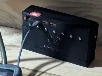
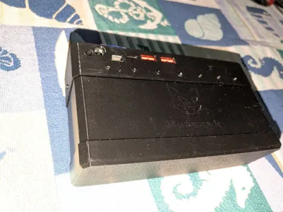
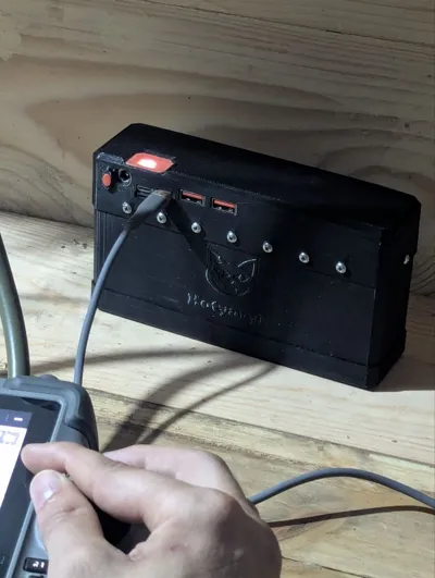
Modular 4S Powerbank Case for 65W / 100W PD Board


Print Profile(1)
Description
Membership
💼 Commercial Use: If you wish to produce this item commercially, I have added a commercial subscription. With an active subscription, you will gain the right to legally sell my models while also supporting me as a developer. A commercial subscription can also be purchased simply for support
Boost Me (for free)
Please support our work 💪
For you, this model downloads in a few seconds, but for me, it represents weeks of work after my main job.
Creating such models takes a lot of time, so your "Boost" costs you nothing but greatly helps me continue developing projects.
And for those who want to support even more – go ahead
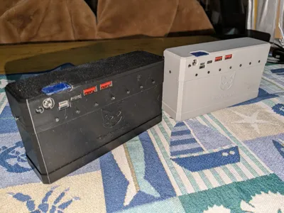
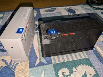
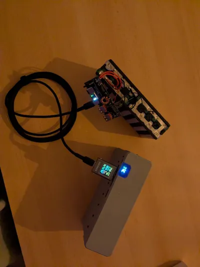
Attention: I personally haven't had time to assemble it yet due to lack of time; the ones in the photos were assembled by volunteers, so the model might still have some flaws, but the prototype is already functional!!!!
V1.4
📌 Description
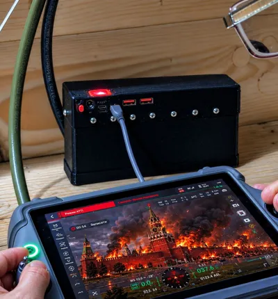
This power bank was fundamentally developed to power Starlink Mini, considering its actual consumption (≈25–40W) and the need for stable operation via USB-C Power Delivery (For Orc-Dinosaurs, Starlink is no longer relevant, let them fire up their Tapiks 😉😉)
With a 4S4P configuration using 18650 2700 mAh batteries, the estimated energy of the assembly is approximately:
- 4S → nominal voltage ≈14.8V
- 4P → 10.8Ah
- Total energy ≈160 Wh
- Considering conversion losses (≈15–20%) → ~130 Wh of usable energy
With an average Starlink Mini consumption of 35–40W, this provides approximately up to 4 hours of autonomous operation
Actual time depends on:
- battery quality and condition
- temperature
- real load
- converter efficiency
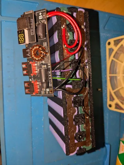
🔌 Why this particular board was chosen
The Diymore PD 65W / 100W board was chosen due to:


- USB-C PD up to 100W
- built-in basic protection
- section voltage control
- DC 5.5 mm input (possibility to charge from a car cigarette lighter)
The ability to charge the power bank directly from a car makes the system more autonomous and versatile
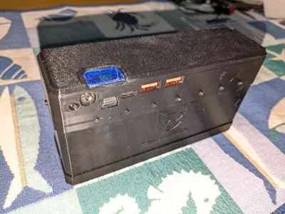
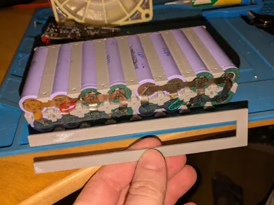
🧩 Case Design
🔹 Board Compartment
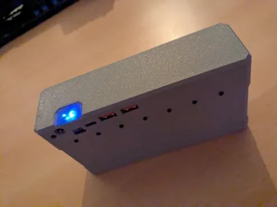
- Precise fit for Diymore PD 65W / 100W (power depends on the quantity of S3, 65 W 4-5 100W)
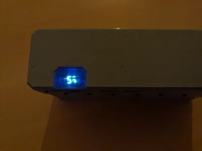
- Opening for the board display
- Display protection against mechanical stress
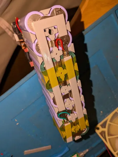
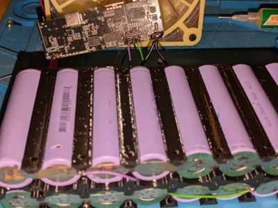
🔋 Battery Module
Basic configuration: 4S4P (18650)
Can be used:
- 18650 of any capacity
- 21700 (with appropriate layout)
- Li-Po packs
- other battery assemblies
The 18650 slots can be removed, and the case becomes a universal battery compartment
🔧 Protection and Operation Without BMS
The board has built-in basic protection:
- against overcharge
- against over-discharge
- against overload
- section voltage control
If using:
- new or lightly used cells
- identical batteries
- correct balanced connection
then this level of protection is sufficient for stable operation for a certain period (one to one and a half years)
The batteries will not fail immediately
For long-term use or with uneven cells, installation of the following is recommended:
- BMS 4S (20–40A)
- or an active balancer 4S
Before connecting, always check the pinout on your specific board
Different sellers may have different revisions and pin numbering
🎥 Video with Board Teardown
I recommend watching a detailed review of this board, where the author:
- assembles the power bank
- disassembles the board
- explains the operating principle
The author thoroughly explained this board
Special thanks to the author KepiVova for the high-quality technical video review of the board, the material, and permission to use this video
📺 Video:
https://youtu.be/q8kJrqJk_EA?si=DrOcbcHO13gz-pMu
📦 Bill of Materials (BOM)
| No | Component | Quantity | Note | Link |
|---|---|---|---|---|
| 1 | Diymore PD 65W / 100W
| 1 | 3S / 4S / 5S version | https://www.aliexpress.com/wholesale?SearchText=Diymore+PD+100W+power+bank+board
|
| 2 | 18650 batteries / and other batteries you can fit | 16 | For 4S4P | https://www.aliexpress.com/wholesale?SearchText=18650+2700mAh
|
| 3 | Nickel strip 0.15–0.2 mm
| ~1 m | For spot welding cells (recommended) | https://www.aliexpress.com/wholesale?SearchText=nickel+strip+0.2mm
|
| 4 | Power wire AWG16
| ~30 cm | For battery connection | https://www.aliexpress.com/wholesale?SearchText=AWG14+silicone+wire
|
| 5 | Balance wires 3S,4S,5S  | 1 set | Can be made independently | https://www.aliexpress.com/wholesale?SearchText=4S+balance+wire
|
| 6 | Screws (M3 or other)
| 4–6 pcs | Choose the correct length | https://www.aliexpress.com/wholesale?SearchText=M3+screws
|
| 7 | (Optional) BMS 3S,4S,5S 20–40A
| 1 | Full protection | https://www.aliexpress.com/wholesale?SearchText=4S+BMS+30A+balance
|
| 8 | (Optional) Active balancer 3S,4S,5S
| 1 | Active Equalizer 1.2A | https://www.aliexpress.com/wholesale?SearchText=4S+active+equalizer+1.2A
|


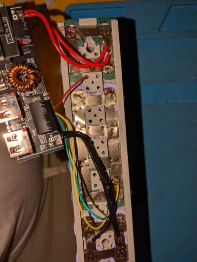
🔌 Balance Cable Connection Diagram
🔋 For a 4S Li-ion battery, the voltage should be approximately as follows
| Pin | Voltage relative to minus |
|---|---|
| B- | 0 V |
| B1 | ~3–4 V |
| B2 | ~7–8 V |
| B3 | ~11–12 V |
| B+ | ~14–16.8 V |
The voltage should gradually increase from minus to plus
⚠️ Very Important — Connection Order
To avoid damaging the board, it is recommended to connect the battery in the following order:
Supported configurations:
- 3S
- 4S
5S

⚠️ Always check the pinout on your specific board
Different sellers may have different revisions and pin numbering
Incorrect connection of balance wires can damage the board or battery
🔌 Board Variants
The Diymore board exists in several versions
Some have an additional DC 5.5 mm input (car cigarette lighter)

Other versions come without this connector

Before printing and assembly, verify the board version compatibility
🔧 Capacity Measurement Resistor (R8) Settings
The board has an R8 resistor, which is used by the controller for approximate determination of the battery pack's capacity
This resistor sets a parameter by which the board estimates how much energy the battery pack can store, and accordingly displays the charge level on the display
⚠️ Important
This does not affect charging operation or battery protection
The resistor affects only the accuracy of the charge percentage display
If the resistor value does not match the actual battery capacity, the display may:
- show 100% for too long
- or conversely, drop quickly to 0%, even though there is still charge remaining in the battery
📌 Standard Value
On most boards, the default resistor installed is:
R8 ≈ 10 kΩ
This value is suitable for small battery packs
🔋 When R8 needs to be changed
If a large battery pack is used (for example 4P4S or more), the charge percentage reading may be inaccurate
In such a case, a different R8 resistor value can be selected to make the display more accurately reflect the charge level
⚠️ This setting is optional — the power bank will work even without changing the resistor
⚠️ IMPORTANT
If you remove the 18650 slots and use other batteries:
- check the screw length
- do not allow the screw to contact the battery
- or secure the cover with glue
Mechanical damage to lithium batteries can lead to a short circuit or ignition
🖨 Printing Recommendations
1️⃣ PETG / ASA / ABS
2️⃣ 5 perimeters
3️⃣ 30–40% infill
4️⃣ Layer height 0.2 mm
5️⃣ Orientation — mounting areas along the layers
License
You shall not share, sub-license, sell, rent, host, transfer, or distribute in any way the digital or 3D printed versions of this object, nor any other derivative work of this object in its digital or physical format (including - but not limited to - remixes of this object, and hosting on other digital platforms). The objects may not be used without permission in any way whatsoever in which you charge money, or collect fees.
Comment & Rating (0)