
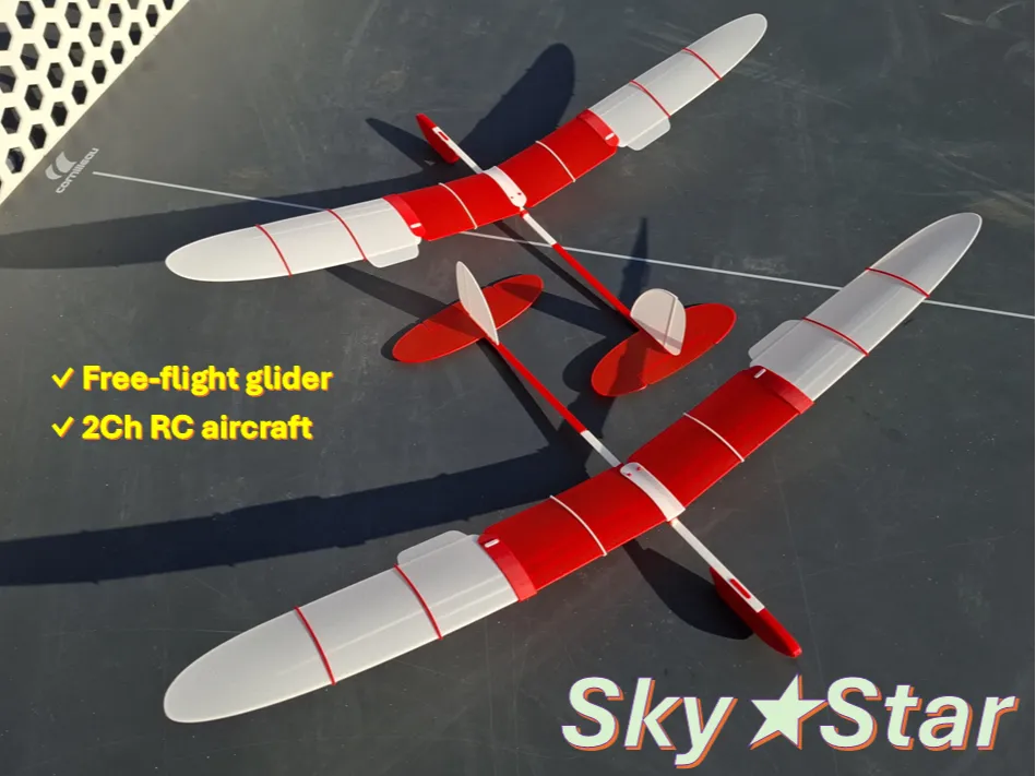
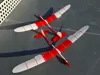
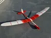
Free-flight glider / RC model "SkyStar"
Print Profile(4)

Bill of Materials




- 2-channel RC parts x 1:
Description
SIMPLE. FLYING. FUN
SkyStar — Evolved Freedom, Expanded Control
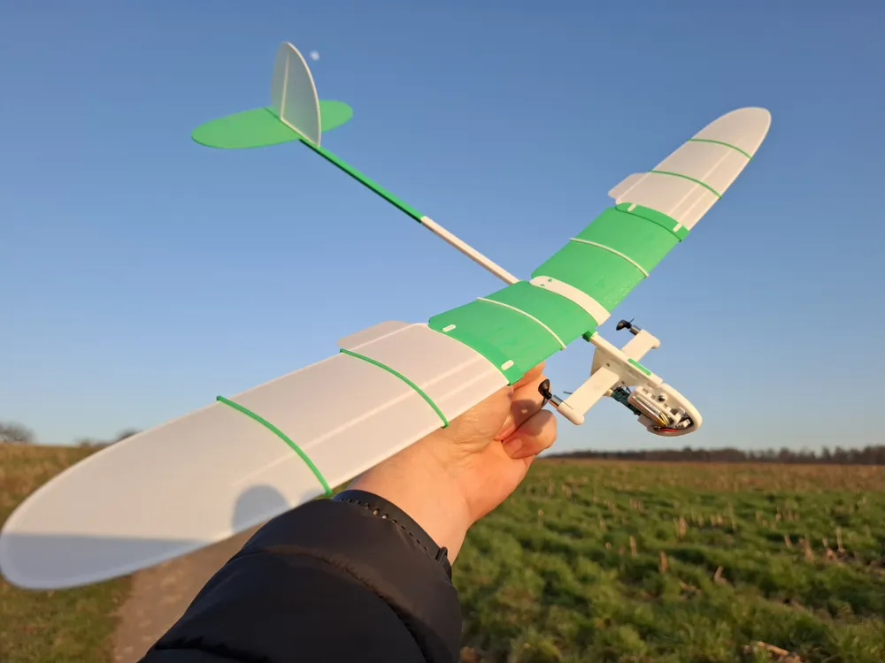
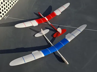
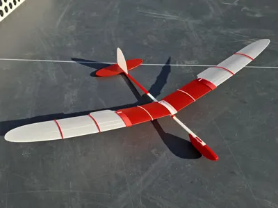
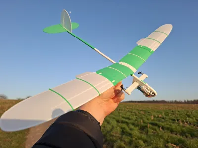
Inspired by the philosophy of “WingStar”, SkyStar takes the concept further by combining refined aerodynamics with greater versatility. Drawing on experience from “Albatross” and the modular approach of “COMET”, this model offers improved glide performance, enhanced stability, and increased structural strength.
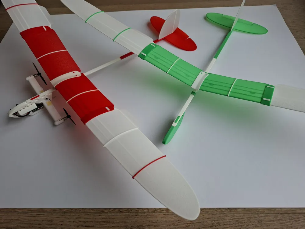
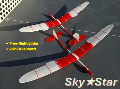
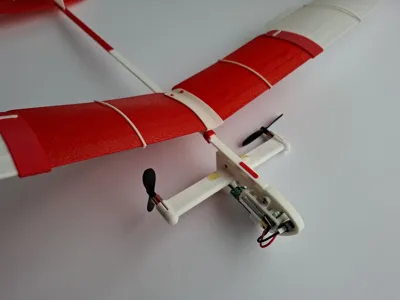
With its extended wingspan and reinforced tail boom, SkyStar delivers smoother, more confident flight characteristics. The design remains modular and adaptable: it can be flown as a pure free-flight glider with removable nose ballast, or configured as a simple 2-channel RC model. Optional ailerons and elevator provide additional control for those who want to explore more advanced flight.
SkyStar preserves the simplicity of its roots — while opening new possibilities in the sky.
1 - Model Description
"SkyStar" is a compact free-flying glider model for outdoor launches in calm weather. Model offers an excellent hands-on introduction to the basic principles of aircraft design, technology and flight mechanics.
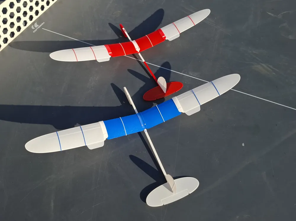
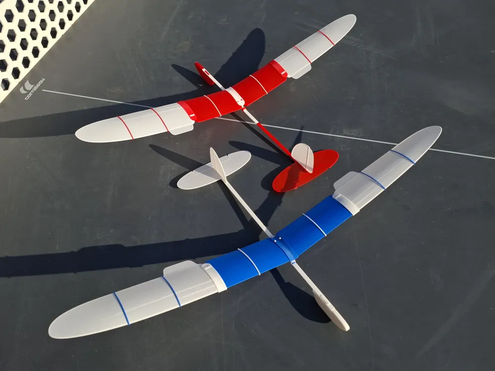
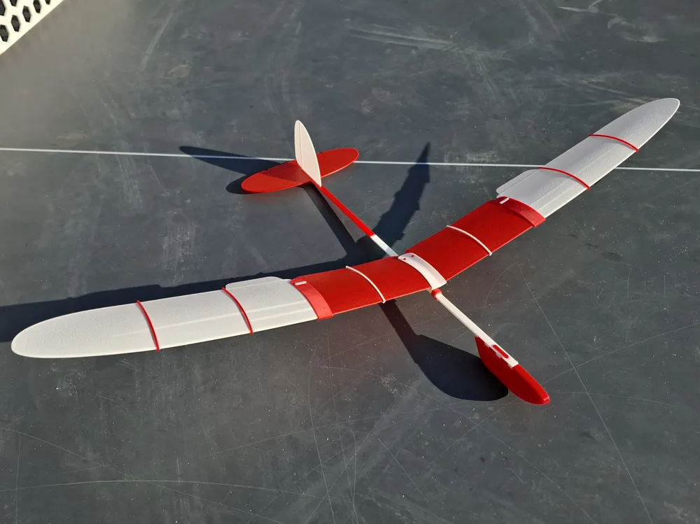
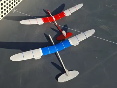
The model has a wingspan of 630 mm, length of 410 mm. Model has an improved design of wing and has a movable wing position. This option provides the ability for very precise adjustment of the model’s aerodynamic focus and center of gravity, ensuring the most optimal, long-lasting, and beautiful flight.
Model presented in 2 Options:
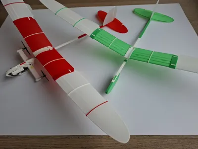
Option A – Free-flight glider, mass 42 gramm.
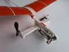
Option B – 2-channel RC model airframe, mass 59 gramm (including RC parts).
2- Materials, Settings, Parts Printing
Model design created and tested with Bambu PLA Basic. Therefore I highly recommended to use this material for your model.
It is NOT recommended to use PLA Matte for the model, especially for wings. Often parts got twisted after removal from the Plate due to internal tensions after the cooling.
Please follow the instruction and recommended print settings.
Note: The print profile for A1 mini has slightly different settings with increased material flow rate. Please print massive part (Nose mass) separately (as proposed in print profile) to minimize negative impact on quality of tiny other parts.
To secure best printing results:
- Don't forget to cleanup printing Plate before print to exclude adhesion problems.
- After printing completion remove the Plate from table, cool down it for 3-4 minutes
3 - Model Assembly
3.1 - Free-flight Glider - Option A (Basic model)
The model (Option A) consists of 17 parts, as shown in Figure below:
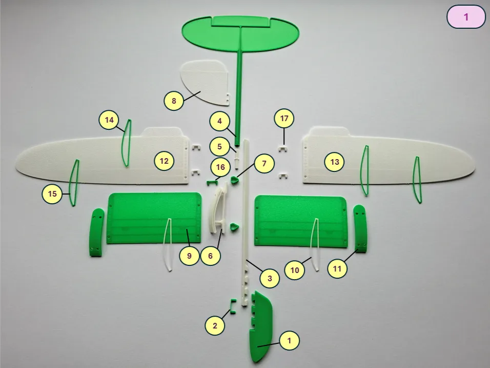
1 – Nose, 2 – Nose connector, 3 – Nose beam, 4 – Tail beam, 5 – Beam connector, 6 – Central bracket, 7 – Wing clamp (2pcs), 8 – Fin, 9 – Wing panel (2pcs), 10 – Wing panel rib (2pcs), 11 – Wing connector (2pcs), 12 – Wing right, 13 – Wing left, 14 – Wing rib big (2pcs), 15 – Wing rib small (2pcs), 16 – Central dual pin, 17 – Wing panel pin (4pcs).
Glue must be used where indicated by a special symbol. It is recommended to perform a first test assembly without glue to understand the assembly principles and check the fit of parts. Final assembly before flight must be done with glue. SuperGlue is recommended.
Assemble the fuselage beam (parts 3, 4, 5, 8, 7).
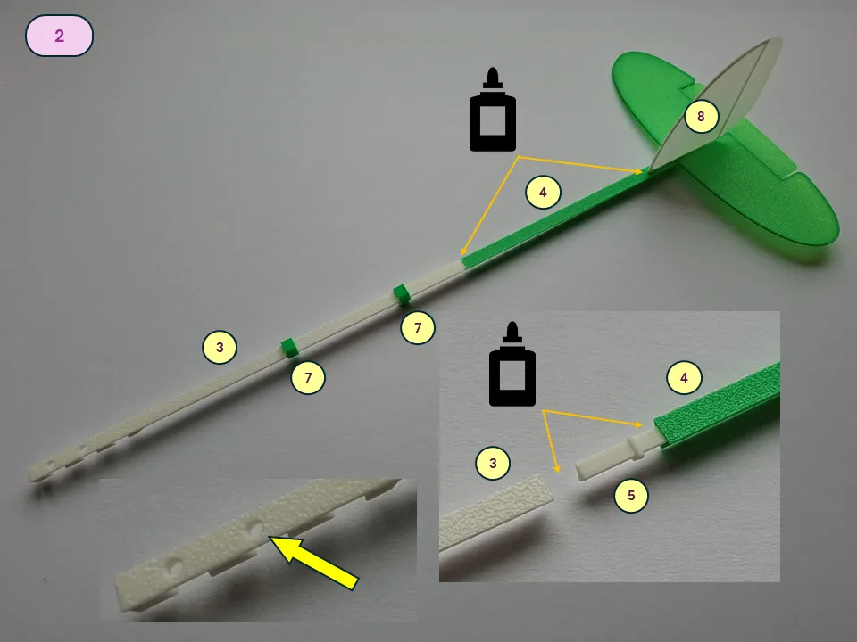
Before final assembly parts 7 (2 pcs) must be mounted on Nose beam (3). Parts 3, 4, 5 must be glued during beam assembly. Pay attention to the proper positioning of part 3, the mounting holes in forward area must be oriented upwards, as in the picture.
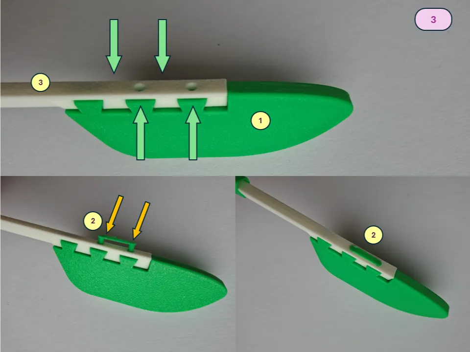
Connect the assembled boom with Nose part (1). Apply slight pressure from side to assemble parts properly. As final step install the Nose connector (2) as shown on picture.
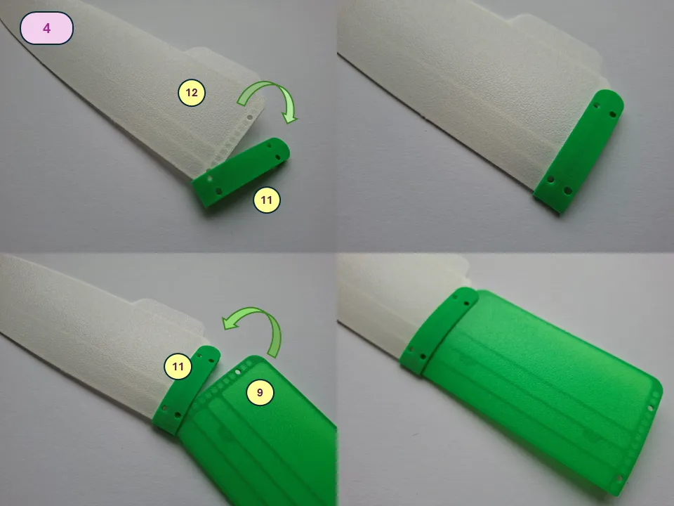
Assemble the Wing. Install the Wing right (12) into the Wing connector (11). When installing the Wing , first insert the front part, then rotate it into its final position. A test fit is recommended before applying glue. During assembly, make sure there are no gaps at the front section and that the parts are aligned correctly, the centers of mount holes are located properly. Install the Wing panel (9) using the same principle.
Install the ribs (10) onto the Wing panel. The ribs are placed into specially designed slots on the leading and trailing edges. Before installation, ensure that the ribs are positioned in the correct orientation relative to the direction of flight, following the curve of the wing bracket.
For the initial installation of rib (10), the panel needs to be slightly compressed to give it curvature, as shown in Figure. After positioning the rib on the Wing panel, slide it toward the center for final installation. A click will be heard when it is properly installed. No glue is used when installing the ribs. After completion install the Wing panel connectors (17) with application of slight pressure.
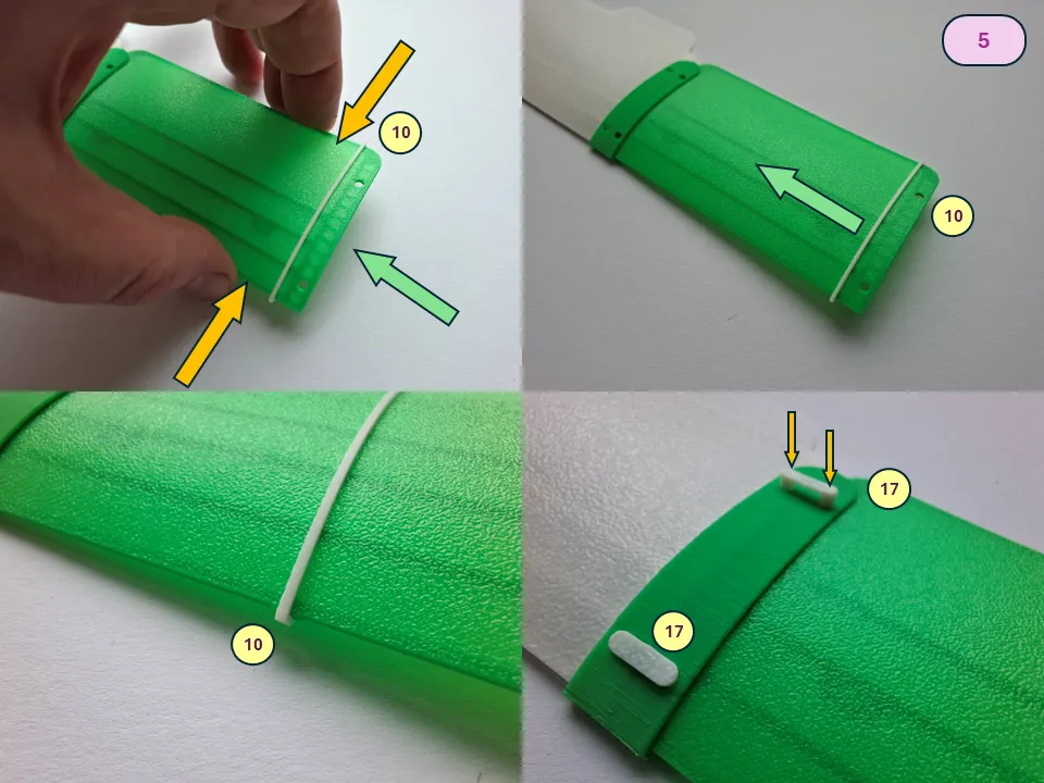
Install the ribs onto the Wing. The ribs fit into specially designed slots on the leading and trailing edges. A click will be heard when they are properly installed. Ensure that the ribs are oriented correctly relative to the direction of flight, following the curvature of the wing bracket. Start with the Wing rib big (part 14), then install the Wing rib small (part 15). No glue is used when installing the ribs.
Install the assembled right wing into the Center bracket (6). When installing the wing, first insert the front part, then rotate it into its final position. A test fit is recommended before applying glue. During assembly, make sure there are no gaps at the front section and that the parts are aligned correctly, as shown on the picture.
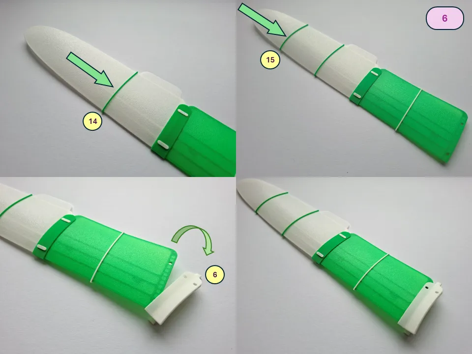
Repeat all Wing assembly steps for the right side, using parts 10,11, 13, 14, 15, and 17. Install assembled left Wing in Central Bracket (6). Use Central dual pin (16) to fix both assembled wings on Central bracket (6).
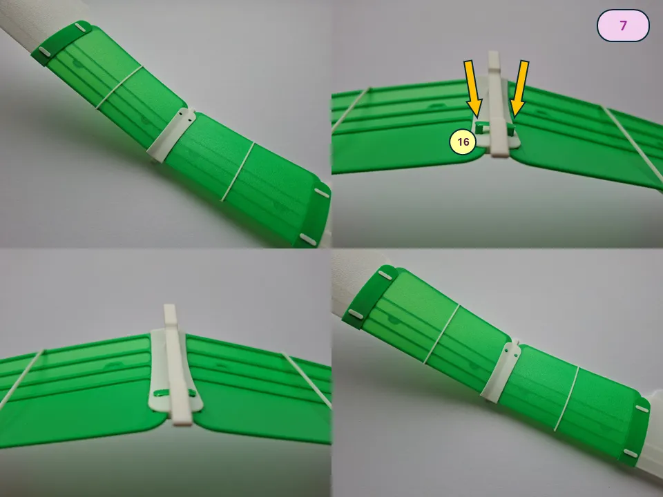
The completed wing should have no warping of the lifting surface and must be symmetrical.
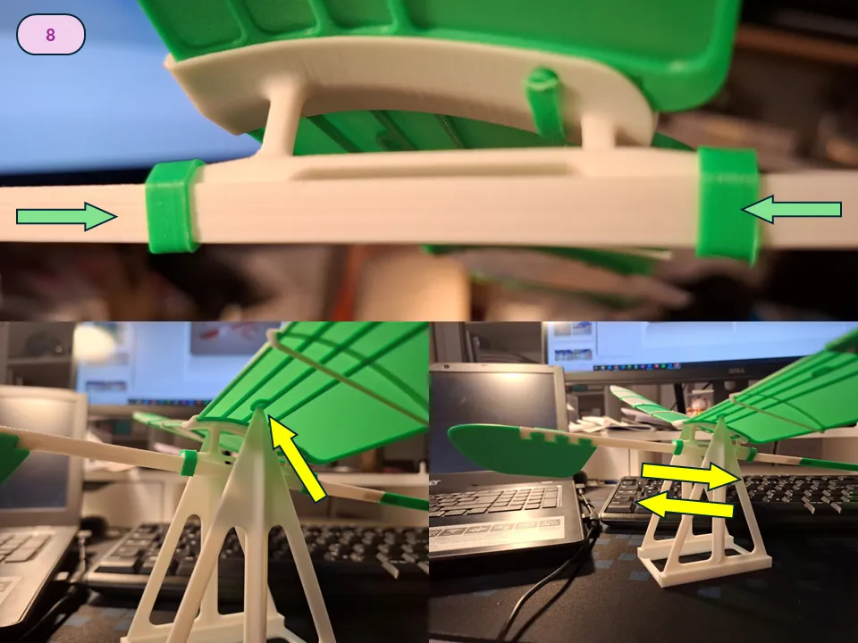
The wing installation is very simple using Wing clamps (7), as shown on the picture below.
The wing can be moved forward or backward if needed, allowing for precise adjustment of the model’s Center of Gravity.
Additionally, if necessary, model components (the wing or fuselage) can be disassembled for convenient and compact transportation or components fast replacement.
3.2 - RC Model Airframe - Option B
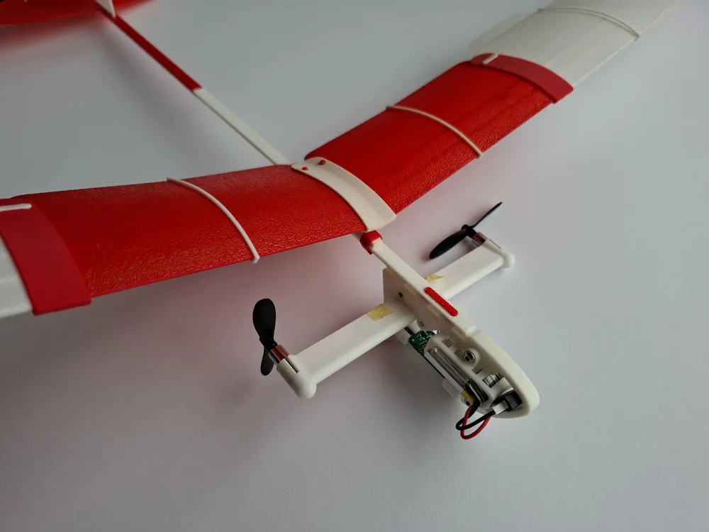
The optional module for conversion of the model into a 2-channel RC aircraft (Option B) consists of 6 parts, as shown in the picture below.
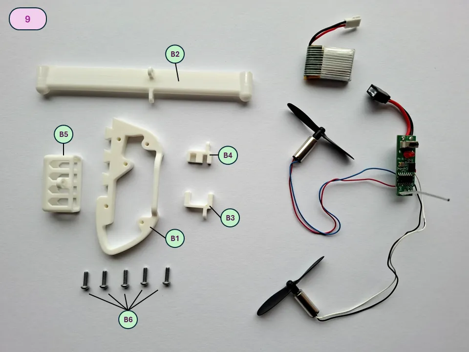
B1 – Nose frame, B2 – Engines beam, B3 – Forward PCB bracket, B4 – Rear PCB bracket, B5 – Battery box, B6 – Screw BHCS M2.5x8 (5 pcs).
Note: The used RC PCB plate has dimensions 38x18 mm. The engine outside diameter is 6 mm. The used 1C battery has dimensions approx. 28x18x7 mm.
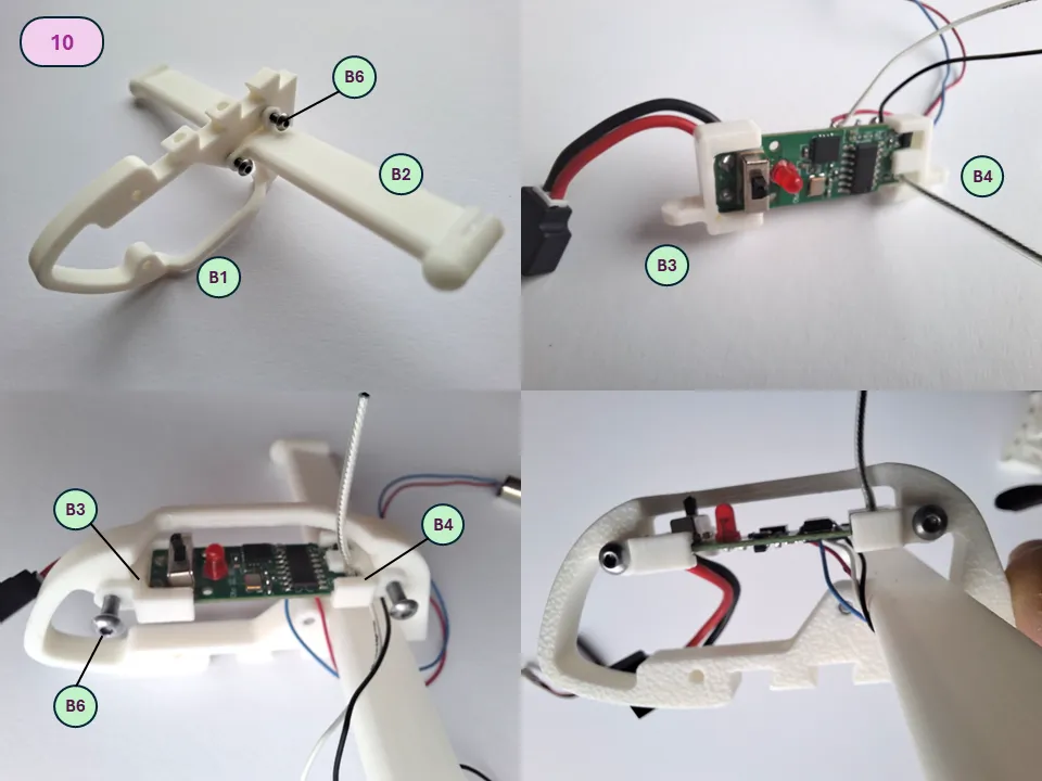
Mount Engine beam (B2) on the nose frame (B1) with use of two screws (B6). Match the Forward PCB bracket (B3) and Rear PCB bracket (B4) on the PCB plate, as shown on picture. Afterwards, carefully mount the assembly on the Nose Frame (B1).
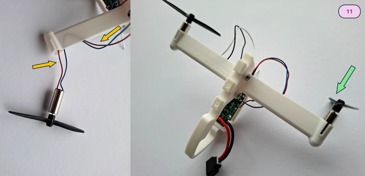
Route the engine wires on the required sides. Pay attention on proper side positioning of engines (direction of rotation).
Bend the engine wires to push them into the Engine beam trailing edge slot. Then install engines on the required side by slight pressure. No glue required.
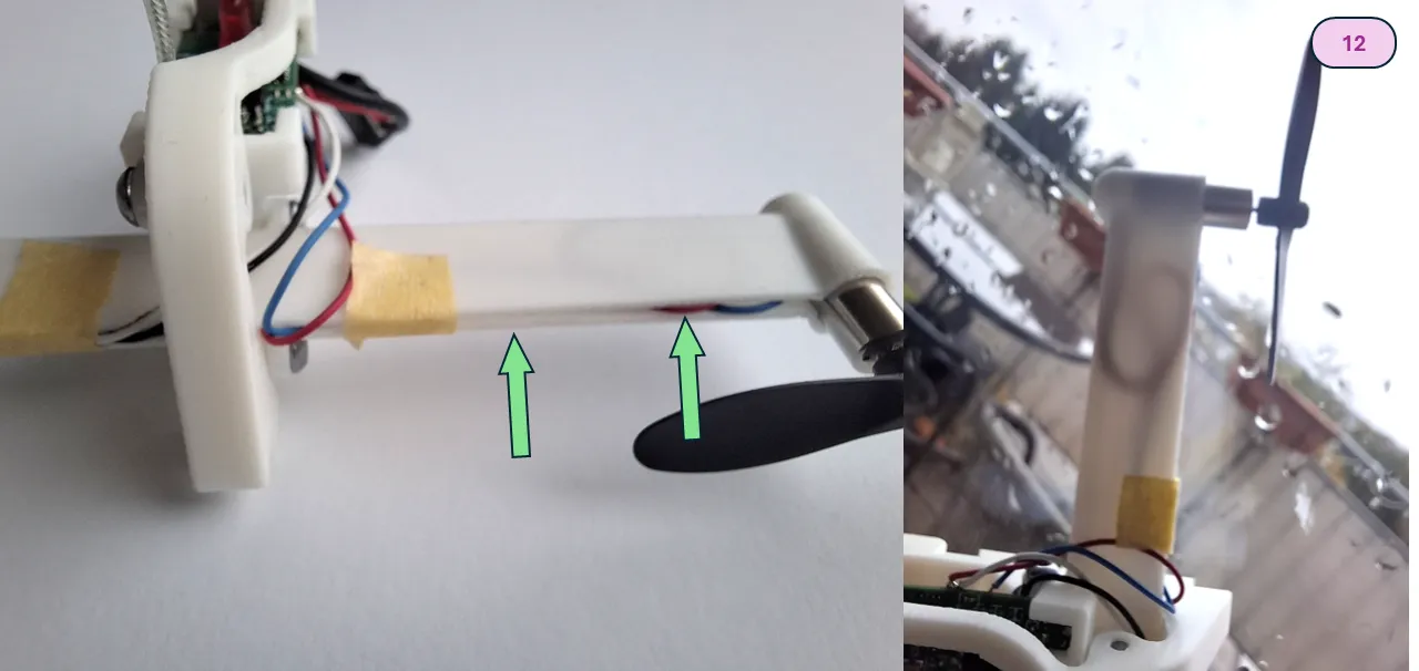
After the completion of engine installation, locate the rest of the hanging wires inside the Engine beam. It is recommended to use a tiny piece of duct tape to fix wires inside.
Install Battery box (B5) with use of screw (B6). After completion of module assembly install it on aircraft Nose beam (3) as shown on picture. Use Nose connector (2) to fix module finally.
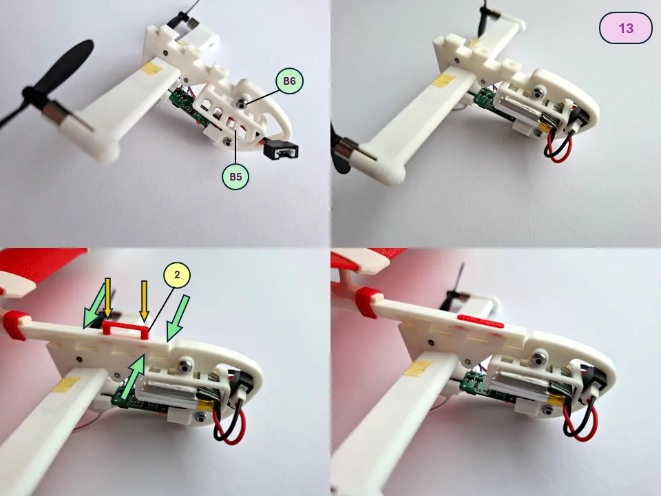
Install the battery, and check the operation of the RC hardware. Check the proper rotation of propellers and the expected reaction (turn) of the model.
After completion of the checks perform the CG balancing (mandatory) as described in Chapter 4.
4- Model Pre-flight Adjustment
Before the first flight, it is strongly recommended to balance the model to expedite its in-flight adjustment. The initial CG position must be adjusted to approximately 16-18 mm from the wing leading edge. Special mounting points for setting up on a balancing stand are provided for initial adjustment, as shown on picture below.
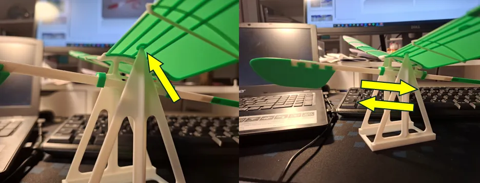
For static balance, simply move the installed wing forward and backward and check the position of the center of gravity on the stand. The balanced model should be in static equilibrium or with a slight nose-down inclination.
The following CG Balancing Stand (as shown on picture) may be used: https://makerworld.com/en/models/912400-model-cg-balancing-stand#profileId-873575
Alternatively, model balance can be adjusted in hands, allocating marked point of wing center sections on fingers.
5 - Model Flight

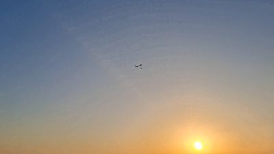
The model is launched outdoors. It is recommended to launch the model in relatively calm weather, with winds no stronger than 9 km/h (2.5 m/s, 5 knots).
The model is launched horizontally or with a slight nose-down inclination (about 2-3 degrees) with a gentle push. The model should be launched directly into the wind.
In case of diving (model with a “heavy nose”) or pitching up, it is necessary to further adjust the position of the model’s center of gravity.
Pitch adjustment is achieved by slightly moving the wing forward (to pitch up in case of a “heavy nose”) or rearward (to pitch down). Also, pitching may be corrected with slight deflection of elevator.
Yaw adjustment is achieved by deflecting the rudder.
Happy Flights and Smooth Landings!
Boost Me (for free)
If you like my models, hit that Boost button like it's a launch switch! 🚀
License

You shall not share, sub-license, sell, rent, host, transfer, or distribute in any way the digital or 3D printed versions of this object, nor any other derivative work of this object in its digital or physical format (including - but not limited to - remixes of this object, and hosting on other digital platforms). The objects may not be used without permission in any way whatsoever in which you charge money, or collect fees.


Comment & Rating (129)