BC-250 case ( internal PSU + 2x 140mm Fans )


Print Profile(1)
Description
Description
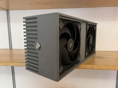
Hi everyone! This is my custom 3D printed enclosure for the BC-250 mining card / Bazzite gaming pc.
I designed this because I wanted a case that fully encloses the board along with the PSU, rather than having parts hanging out. My main goal was airflow, unlike some other models out there, this case ensures air is forced through all the components, including the backplate which often gets neglected.
Key Features:
- Full Enclosure: Fits the BC-250 and a Meanwell LOP-400-12 PSU inside.
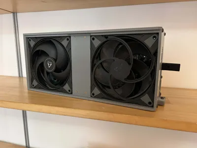
- High Airflow: Designed for two 140mm fans (push/pull config) to keep temps down.
- Backplate Cooling: The design allows for a 120mm heatsink on the back, and the airflow path actually covers the backplate area.
- Cable Management: There’s a dedicated hole on the top for clean cable routing or for using 180-degree adapters.
A Note on My Setup: To get the best performance, I repasted my BC-250 with PTM7950 and used UTP-6 putty, now heats is getting transfered more easily.
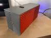
Disclaimer: The photos show an earlier prototype. The files included here are slightly updated versions with better fitment, so don't worry if a small detail looks slightly different from the picture.
Bill of Materials
- PSU: Meanwell LOP-400-12
- Fans: 2x 140mm fans (max 27mm thick)
- Inserts: M4 and M3 Threaded Inserts
- Screws: M4 and M3 screws (various lengths)
- Power: 10A 250V IEC C14 Socket with Single Fuseholder
- Glue: Superglue or CA glue for body assembly
- Optional: 120x120x20mm Heatsink for the backplate + thermal glue
- Material: PETG - or materials with better heat resistance
Assembly Instructions
Step 1: Prepare the BC-250 Board
- Remove the two existing screws and the metal bracket on the front of your BC-250.
Replace them with two long M4 screws and the printed [BC-250_locking_clip].

Step 2: Prepare the PSU
Use M3 screws and inserts to mount your Meanwell PSU to the [BC-250_LOP-400-12_clip].

Slide the [BC-250_LOP-400-12_clip] onto the backplate of the BC-250.

- Connect your AC wiring and the 12V 8-pin plug now.
Optional but recommended: Use thermal glue to attach a 120x120x20mm heatsink to the backplate.

Step 3: Assemble the Main Body
- Install M4 heat-set inserts into [BC-250_Main_body].
If you are using a front button, install it into the [BC-250_Front_plate] now.

Glue the [BC-250_Front_plate] and [BC-250_Main_body] together.

Install M4 inserts into the back of [BC-250_Back_body].

Glue the Front assembly and Back assembly together. Let it dry completely!

Step 4: Final Assembly
Once the glue is dry, slide the BC-250 board (with the PSU and Clip already attached) into the case from the rear. NOTE: its best to remove top parts of the heatsink for better cooling.

Secure the card to the body using the locking clip and long M4 screws you installed in Step 1.

Install the M4 insert on the tail of [BC-250_Back_plate].

- Mount your two 140mm fans.
- Front Fan: Intake (blowing in).
Back Fan: Exhaust (blowing out).

Glue [BC-250_sidepanel_front] to [BC-250_sidepanel_back]. Slide these assembled panels into the case slots.

Put the [BC-250_Back_plate] on and screw it into the case with 4 M4 screws. This locks the side panels in place.

Secure the I/O bracket to the back plate with a single M4 screw.

Assembly Tips & Cable Management
Test Before You Glue! My assembly instructions above are just for building the plastic shell. Before you glue the main body parts together (and definitely before you close the case), wire everything up loosely and test that the system boots and fans spin. It is much harder to fix a soldering mistake once the case is glued shut!
Cable Management inside the case It's tight in there, so plan your routing carefully. You need to manage:
- The 8-pin power connector for the BC-250 (plus any adapters/extensions).
- The AC wires coming from the back (socket mount).
- The Fan cables (you’ll likely need a Y-splitter).
- The front button wires (if you installed one).
Final Check Ensure no wires are touching fan blades and, most importantly, ensure no AC wiring is touching the low-voltage components or the PSU casing. Double-check your insulation.
⚠ IMPORTANT SAFETY WARNING ⚠
READ THIS BEFORE STARTING: You are dealing with Mains Voltage (110V / 230V). This is dangerous.
- Do this at your own risk. I am sharing how I did it, but I take no responsibility for any damage or injury.
- If you are not comfortable soldering high-voltage wires or understanding grounding, please ask a professional for help or do not attempt this build.
- Insulate everything. Any exposed metal or loose wire strand can cause a short circuit against the BC-250 or the PSU.
Wiring & Electronics Guide
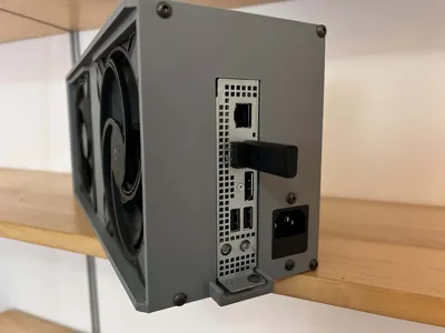
1. The Back AC Socket
I didn't design a universal mount for the AC socket because there are too many different types out there. Instead, the case has a generic cutout with two screw holes.
- My method: I used the socket shown in the attached photos. I secured it using a mix of screws, superglue, and even melted some plastic to fuse it in place.
Your turn: You might need to model a small adapter plate for your specific socket, or get creative like I did.

2. AC Wiring (The "Live" side)
To save space and ensure a solid connection on the Meanwell LOP-400:
- I removed the stock 2-pin AC connector from the PSU.
- I soldered the Live and Neutral wires directly to the PSU board pads.
- Crucial: I covered these connections with a lot of liquid electrical tape to prevent any shorts.
3. Grounding (Safety First)
- For safety, I used a grounded socket (3-pin).
- The LOP-400-12 has 4 mounting holes, and 3 of them are grounded.
- I crimped a ring terminal onto my ground wire and screwed it tightly into one of the PSU mounting holes (secured by the clip screw). Do not skip this step.
4. 12V Wiring (Going to the BC-250)
- I used a standard PCIe 6+2 pin cable.
- I stripped the ends and separated them: twisted the 3 positive wires together and the 3 negative wires together.
- I crimped them into two separate ring terminals and screwed them into the LOP-400 output terminals.
Let me know of any issues, I will try my best to fix tem in next versions.
Thank you to @torassk_228791 for his model of BC-250 it helped me a lot designing the case.
Comment & Rating (4)