Search models, users, collections, and posts

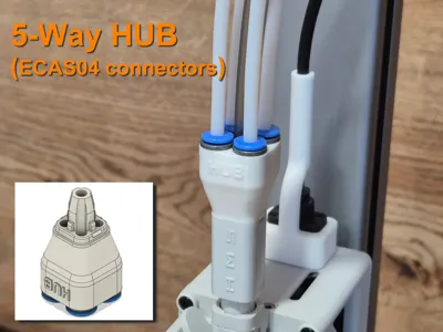
A1 5-Way AMS Hub with ECAS04 connectors

Print Profile(3)

All
A1
H2D Pro
P1S
H2S
X2D
H2D
H2C
A1 mini
X1E
P2S
P1P
X1 Carbon
X1
A2L

0.12mm layer, 3 walls, 25% infill
Designer
1 h
1 plate
5.0(45)

5-way-hub with PC4-M6 connectors
1.1 h
1 plate
5.0(7)

0.08mm layer, 6 walls, 20% infill
5 h
1 plate
5.0(2)

Open in Bambu Studio
Boost
522
1518
115
42
775
644
Released 

Bill of Materials

Bambu Filaments
Select all
Jade White (10100) / Refill / 1kg
List other parts
  • ECAS04 Connectors x 4:

Description

Lightweight 5-way filament hub with ECAS04 connectors.

Why do you need a 5-way hub? Once you start using an AMS (Lite) or BMCU, you may notice that printing from an external spool becomes dramatically inconvenient. You have to disconnect one of the PTFE tubes from the AMS Lite Hub and replace it with a tube from the external spool.

This problem can be solved by using a Y-splitter or a 5-way hub.

I printed and tested plenty of existing variants — none of them satisfied me, and finally I had to design my own version.


Key features of this design:

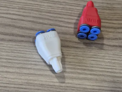
  1. Lightweight. The printed part is only 7 g, and the overall weight, including four ECAS04 connectors, is 12 g.
  2. PTFE tubes are securely fixed and don't slip out during filament changes.
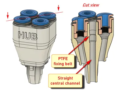
  3. All channels are smooth, and the center channel is completely straight, which is important when printing with TPU.
  4. The entire hub retains freedom of vertical movement, that is, the filament tangle detection function is not blocked.

HowTo:

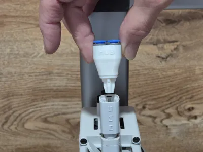
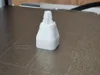
1. Print the 5-way hub and check the channels - they must be clean. Then insert the ECAS04 connectors until they stop, as shown in the photo


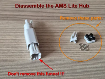
2. Eject and disassemble the original AMS Lite Hub. How to do this - see Bambu Lab Wiki. Remove 3 parts, as shown in the photo. Don't remove the funnel - leave it in place. 

Then insert the lower part of the original AMS Lite Hub with the funnel into its base.


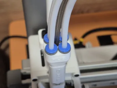
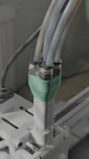
3. Insert the printed 5-way hub into the lower part of the original AMS Lite Hub until it clicks. Pay attention to the mark “HUB” on the printed 5-way hub - it must be on the front side. You should hold the lower part firmly while inserting the printed hub.


Then insert the PTFE tube from the external spool into the central hole. The central channel has a PTFE fixing belt inside, so the tube end should pass through this belt and rest against the rim. It takes about 12 mm of the tube. You will feel a slight click as the tube passes through the belt.


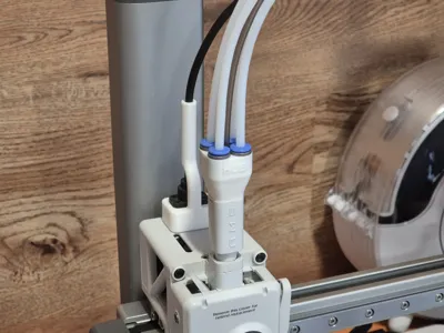
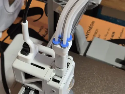
After that, insert four PTFE tubes from AMS (BMCU) in the ECAS04 connectors.


If you use PTFE tube clips (for 5 PTFE tubes), pass the central tube through the central clip hole prior to inserting this tube into the hub. 

If you're not too concerned about the added weight of the print head and prefer greater reliability and stability, you can add a support structure (the Hub Assistant) to this hub. 


Good luck with printing!


Comment & Rating (115)

(0/1000)

This was the only 5 way Ams Hub modification that worked flawlessly. I tried many others including Y Spltters which don't actually ever work. This is because the filament does not withdraw enough to allow you to push the External filament through. As this uses some the internal parts of the original Hub, the filaments swap effortlessly and I can always use the External Spool without having to touch the others. This designer needs major credit for this design as I have spent weeks trying to solve the effortless 5 way options. Thank you. I want to give a Boost for this as it is the only one that works but I didn't seem to get the 2 from the start. I have a Support Arm lest in from another attempt that fits perfectly to help support this one. Once again thank you very much.
(Edited)
The designer has replied
7
Reply
Thank you very much! It's a pleasure to read...
1
Reply
This hub assistant looks pretty stable and doesn't interfere with my cable mod. Would you be able to share it?
2
Reply
Hi, I'm still quite new here and having massive problems and difficulties with my hub. This one seems almost perfect. But I would also be really interested if you could please provide me with a link for the additional support. The possibility to screw it on additionally is brilliant and exactly what I would need. Thanks 🙏🏻
Show original
0
Reply
I'm having the same issue as a few other people, the ECAS 04 connectors I got don't fit. No matter how hard I try I cannot get them in further than the picture shows. I tried heating the hub up in the oven to make it a bit pliable but still they would not fit. All I have managed to do so far is destroy 2 hubs by bending the entire hub out of shape wile trying to press in the connectors. Are there different types of ECAS 04 connectors?
0
Reply
Maybe plastic ones would work better.
0
Reply
Friend, just make the wholes larger, it's not rocket science. You can enlarge the holes from the STL in Blender or even just drill them out to a slightly larger size. That being said, modifying the mesh requires no tools. If you don't know the diameter of your connector, print out a caliper.
0
Reply
it started printing good, but then later it just started printing everywhere. I will try again and see what happens.
0
Reply
probably just bed adhesion issue, did you try again?
0
Reply
Replying to @user_1346055047 :
yes I tried to print it two or three times
0
Reply
So much neater and looks like it just should of been on there from the start. One question the centre tube should pass through then stop I assume as I'm not sure I have pushed it in enough and I never heard a click?
(Edited)
The designer has replied
0
Reply
Thanks for the boost. The central tube end should pass in for about 12mm. And you don't hear a click, you can feel it a little. I think, if you've passed the tube with a little force until it stops, it's quite enough.
0
Reply
Replying to @Sasver_ukr :
Thanks, I think it's in ok then
designer
1
Reply
Print Profile
0.12mm layer, 3 walls, 25% infill
(Edited)
The profile uploader has replied
1
Reply
I'm sorry, but I noticed two issues in your assembly that may lead to undesirable consequences 1 - The 5-Way Hub is installed in the rotated position. The original hub has three slots (from the left, right and rear sides), and the 5-Way Hub has three corresponding tabs to lock in these slots. These tabs are easy to miss, so I specifically marked the front side of the hub with the 'HUB' label and emphasized the need to pay attention to the position of this label in the instructions. In this position, as in your photos, the hub is fixed only at two points (on the back and on the left side) and can slide out of the socket.
(Edited)
3
Reply
Replying to @Sasver_ukr :
2 - You use the PTFE Holder (The hub Assistant) that doesn't fit the 5-way hub in height. I can see that the ECAS connectors rest against the Assistant's shelf, which will not allow you to remove the tubes if necessary - for example, if the filament breaks and gets stuck. More importantly, this Holder probably does not allow the hub and tubes to move freely in the vertical direction relative to the print head, which blocks the Filament Tangle Detection function. This feature is especially important when printing from an external spool. If it does not work, it can lead to filament breakage and even damage to the extruder gears. To avoid these problems, I would recommend using a holder (Hub Assistant) that was specifically designed for this project. The link to it is in the description.
(Edited)
3
Reply
Thanks for the design and upload. Works better then the OEM. No more fighting to get the tubes out! Solid print and good instructions.
The designer has replied
0
Reply
Many thanks.
0
Reply
For the people whose ECAS04 connectors don't fit: I think the designer used the plastic version of the ECAS04 connectors (plastic housing). I've bought ones with a metal housing, but since they won't give way as much as the plastic ones it doesn't go in with a little force. They are meant for metal parts. I've jammed them in anyways, which has bent/damaged the part somewhat (see pic). I'll attach to this post if it still works. Another method could be heating the plastic up slightly before inserting, but I have not tried that yet.
The designer has replied
0
Reply
Quote: "I think the designer used the plastic version of the ECAS04 connectors (plastic housing)" As far as I remember, they were with metal housing. I took them from Aliexpress. Maybe you've bought some different version. I'm really sorry.
(Edited)
1
Reply
Print Profile
0.12mm layer, 3 walls, 25% infill
Great idea that works great. Using the ECAS04 connectors is perfect for this - they're much lighter and lower profile. This setup makes it so much easier to slide TPU down the middle for minimum friction.
1
Reply
printed the version with pc-m4 connectors. had to take a drill bit an chamfer the start of the threads to get the connectors to start threading in. works great tested all 5 ports with loading and unloading.
0
Reply
Print Profile
0.08mm layer, 6 walls, 20% infill
Perfeito
0
Reply

License

This user content is licensed under the MakerWorld Exclusive License.

You may create derivative works based on this object, provided that all such derivative works are published exclusively on the MakerWorld platform and include proper attribution to the original creator. You may not share, upload, host, distribute, or publish this object—or any derivative work of this object—on any other digital platform, marketplace, or distribution channel. Commercial use of this object and any derivative works is strictly prohibited. This includes, but is not limited to, selling, renting, sublicensing, or using the object in any context in which you receive monetary compensation or other financial benefits.