
Kinetic Manta Ray - Biomimetic Automata
Print Profile(2)
Bill of Materials





Description
Boost Me (for free)
Your support motivates me to pursue more exciting creations! Thanks.
Membership
If you have commercial sales needs, you can subscribe to digital authorization for a small amount to support me. Thank you.
Kinetic Manta Ray - Biomimetic Automata
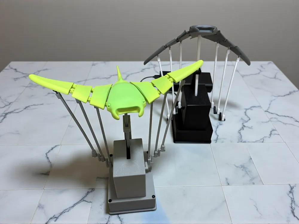
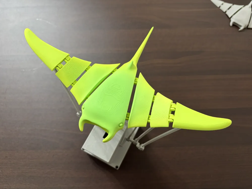

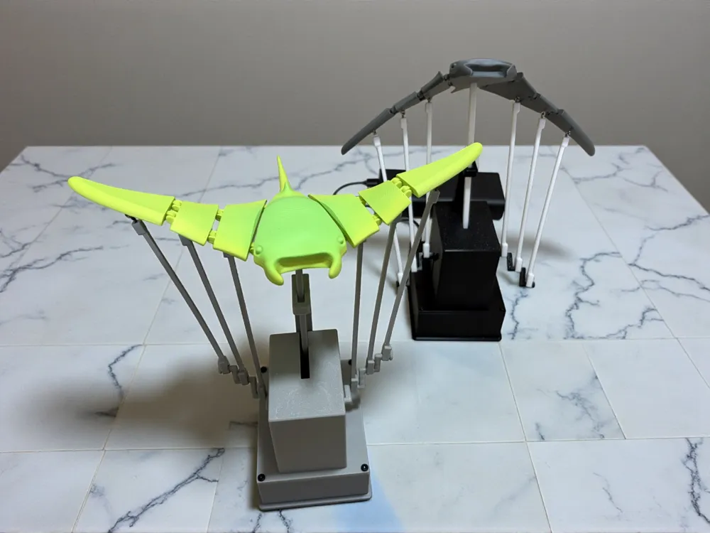
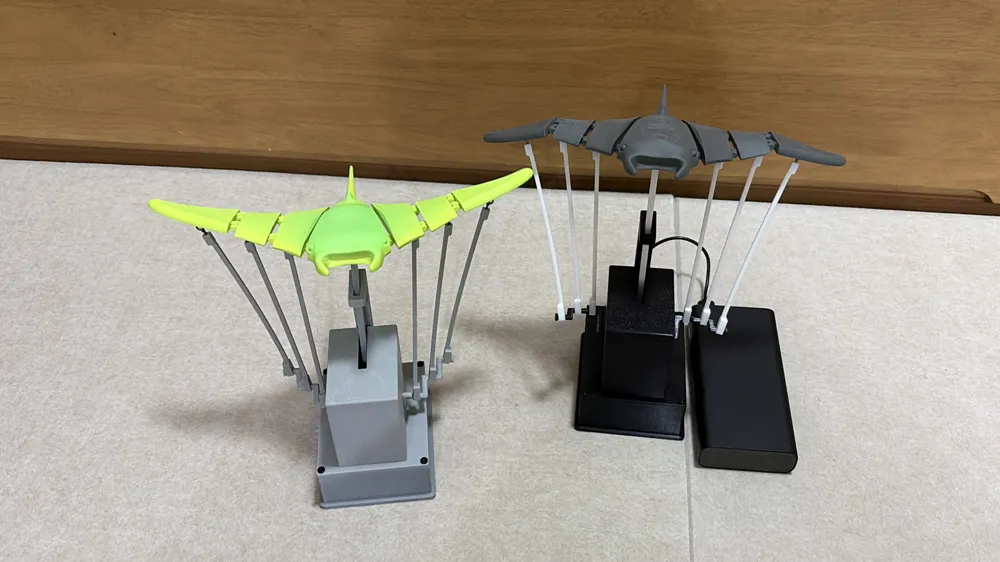
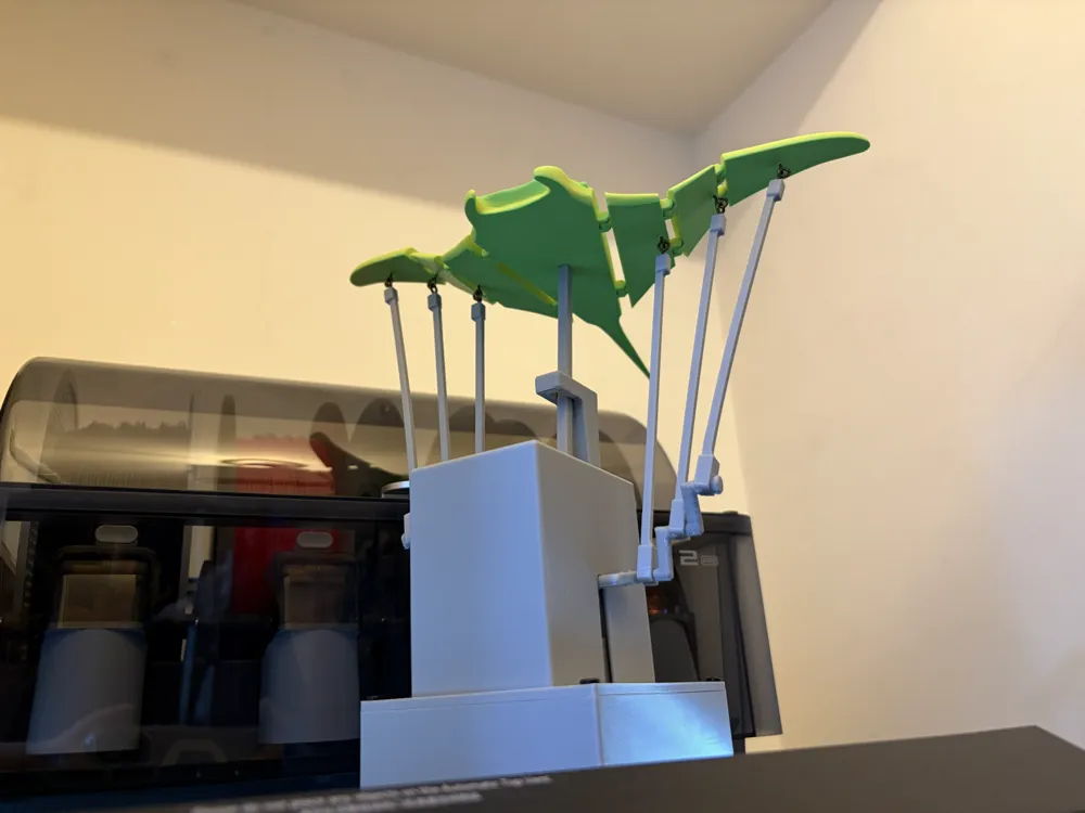
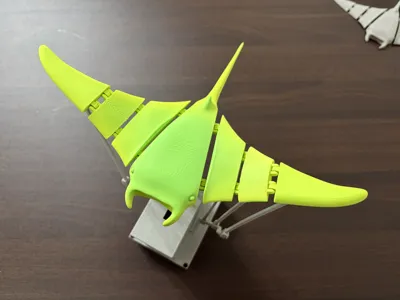
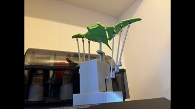
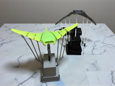
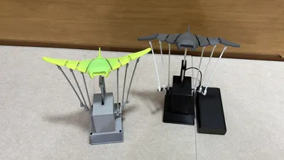
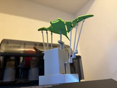
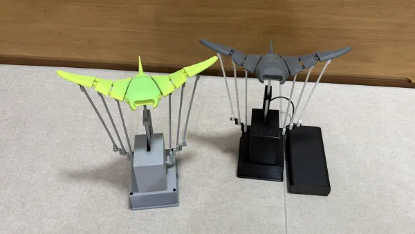
This animated manta ray showcases its graceful movement in the ocean. Through a multi-point linkage system, this piece simulates the rhythmic and fluid undulations of a manta ray's wings as it swims.
I designed two base configurations: a simple battery-powered version or a USB-powered version with adjustable speed, depending on the parts you have available.
Universal parts:
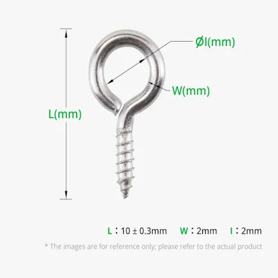
Eye Bolt with Self-Tapping Thread 1.0x4x10 mm x12 pcs
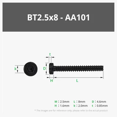
BT2.5 Socket Head Cap Self Tapping Screws (SHCS) BT2.5x8 x8 pcs
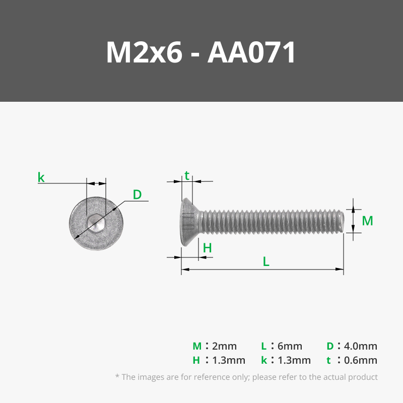
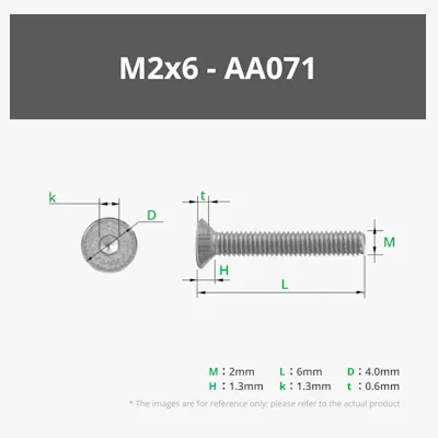
M2 Flat Head Cap Machine Screws (FHCS) M2x6 x4pcs or 8pcs(USB Adjustable Speed Version)
You can also use similar eye bolts and screws from other brands.
Other stationery and tools:
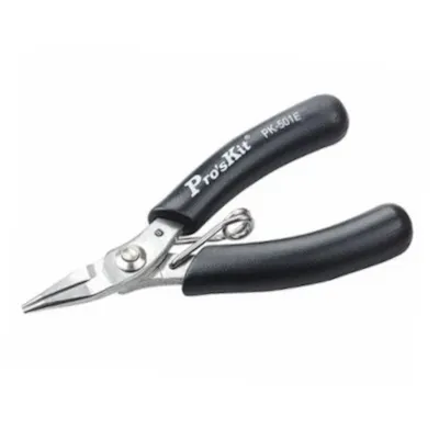
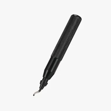
needle-nose pliers、CA glue、Trimming Tool、Hand Drill
 |  |  |  |  |
Hardware List (Please select according to dock version):
A. USB Adjustable Speed Version
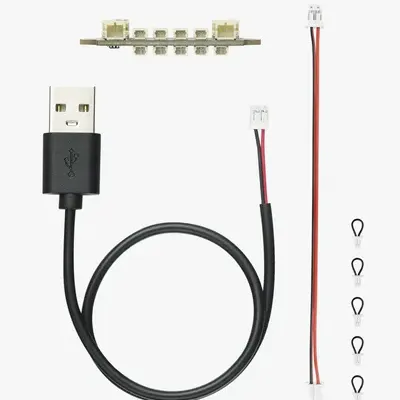
1. Power Distribution Board - 4 Channels (1PCS) - IA005
 |
|
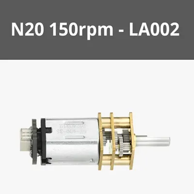
2. N20 Reduction Gear Motor (150rpm is best)
 |
|
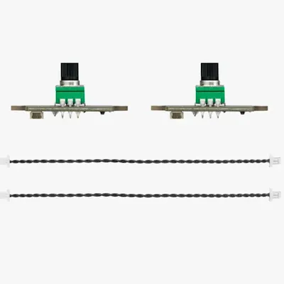
3.Potentiometer Board with SH1.0 Connector
 |
|
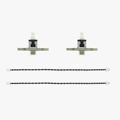
4.Self-Locking Button Switch (2PCS) - IA006
 |
|
B. Battery Standard Version
1. N20 Reduction Gear Motor (150rpm is best)
|
|
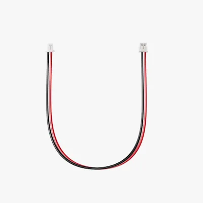
2. 150mm ZH1.5 to SH1.0 Conversion Wire (It's cheaper to buy a Rechargeable Power Kit by adding it to your cart.)
 |  |
3. Rechargeable Power Kit (Note: The 500rpm motor included in the kit is too high; please purchase the 150rpm version separately.)
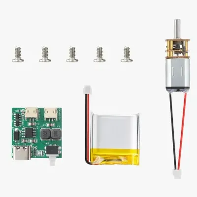 | Charger Board 902525 3.7V 500mAh LiPo Battery N20 Reduction Gear Motor 500rpm M1.6x3 Cross Head Machine Screw |
Kinetic Manta Ray - Full Assembly Guide
Step 1: Wing Mechanism
Parts Prep:
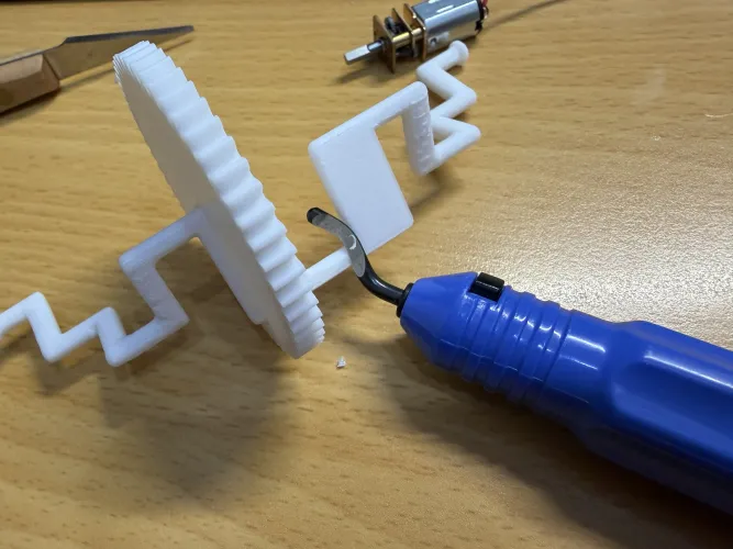
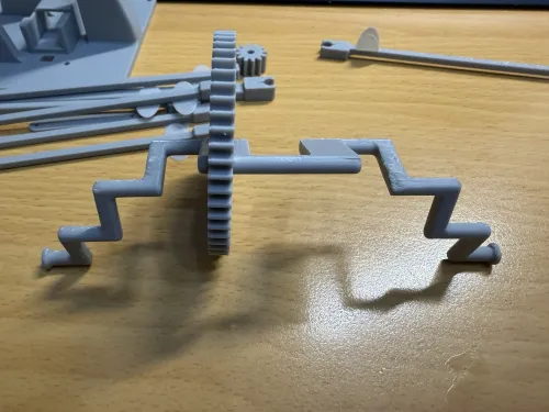
Carefully remove supports from the linkages and other parts. Use a hobby knife or nippers to trim everything flush, ensuring all moving joints are burr-free.
Hinge Assembly:
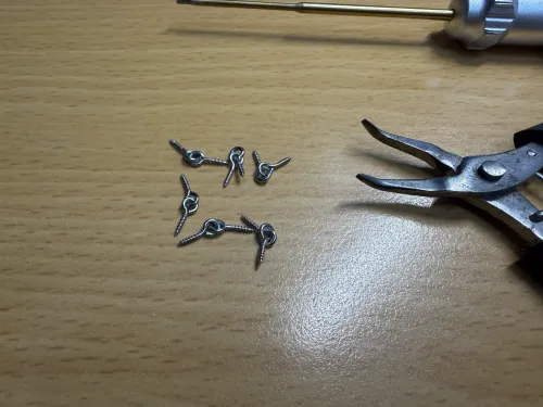
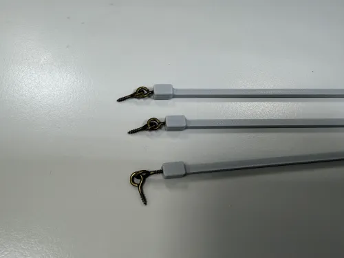
Use needle-nose pliers to interlock the Eye Bolts. If necessary (e.g., loose fit), apply a small amount of glue to secure the screws where they seat into the wing segments.
Step 2: Drive System (Motor & Cam)
- Crankshaft Assembly:
- Clean all supports from the crankshaft. Ensure every pivot point rotates freely.
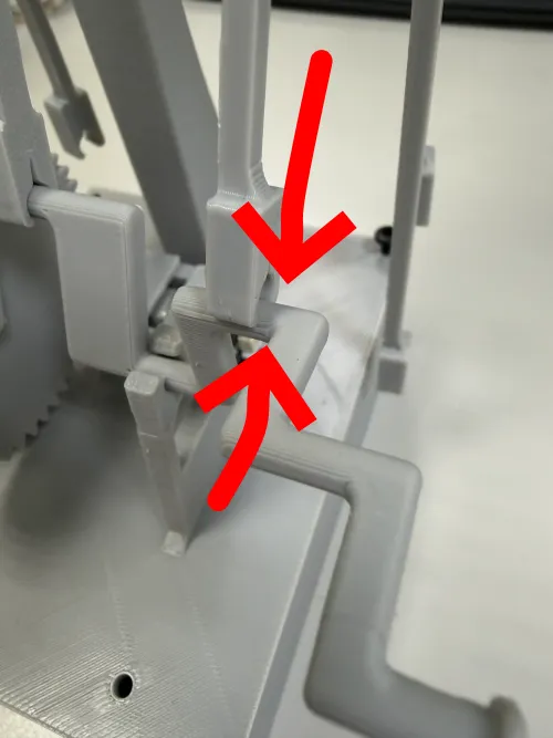
- CRITICAL: Use CA glue to fix the cam to the crankshaft. The angle between the cam and crankshaft must be perfectly perpendicular (90°) to prevent irregular movement or binding.
Press the completed cam assembly onto the motor's D-shaft. Manually spin it to ensure smooth rotation.
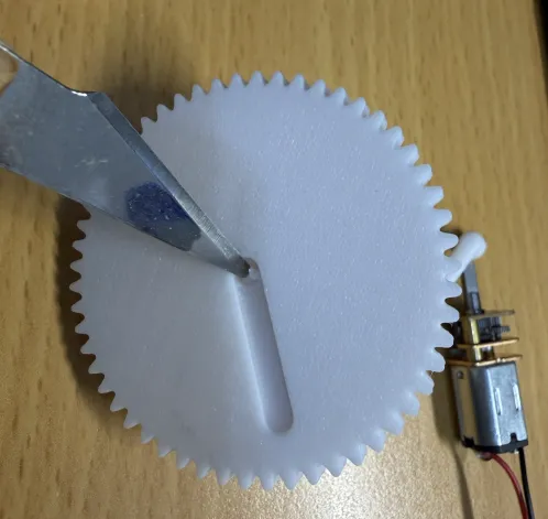
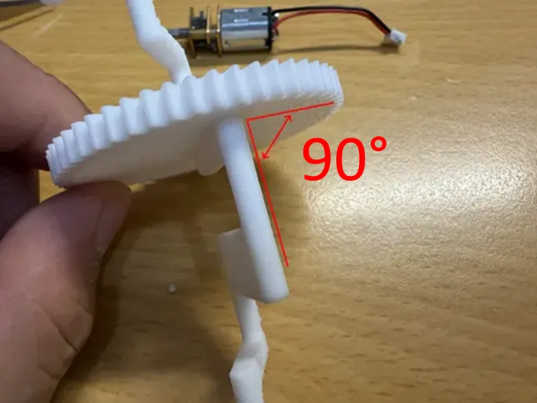
Cam must be at exactly 90° to the crankshaft
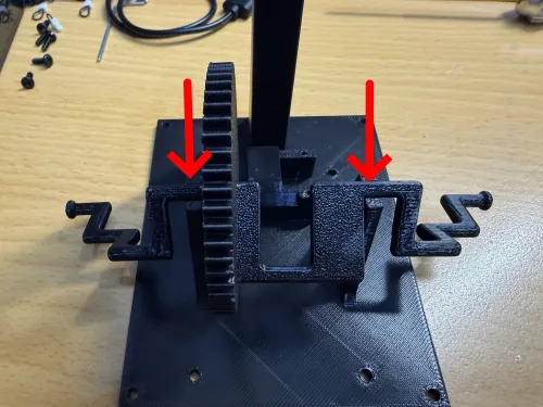
Motor & Gear Installation:
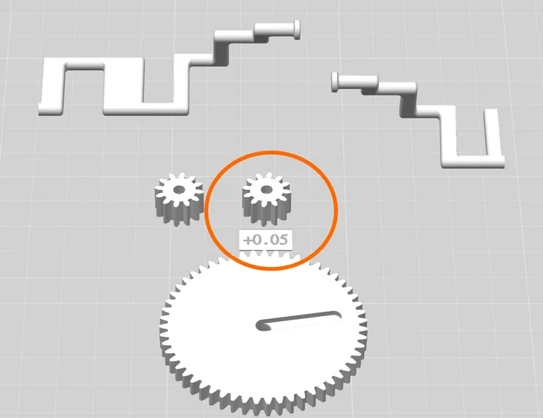
4. Press the N20 150rpm motor into the base. Install the 12T gear; note that the gear hole has a specific orientation (refer to the diagram).
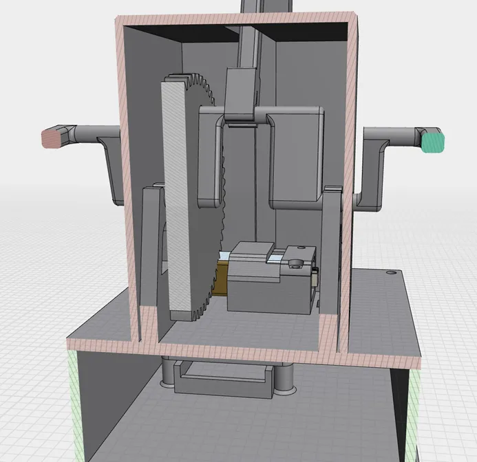
5. IMPORTANT: When installing the motor cover, M2 screws must NOT protrude beyond the cover, or they will obstruct the cam's rotation.
6. Ensure the motor does not extend past the indicated red line to avoid interference with the main housing.
7. Secure the outer cover with M2.5 screws.
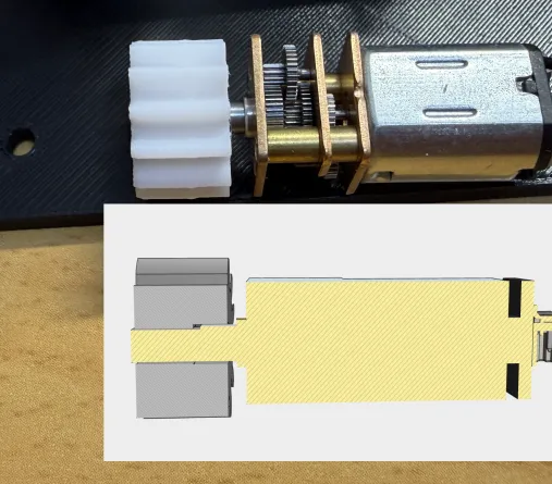
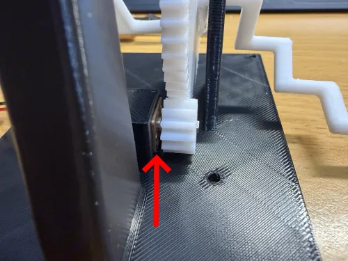
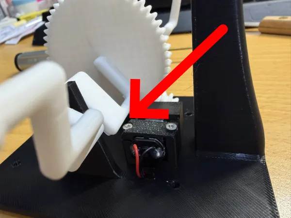
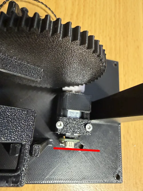
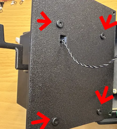
Print plate 3 is equipped with two 12T gears, +0.05 is for use with materials where the holes printed on PLA are too small.
 |
The connecting rod has a 1.5mm redundancy space on both sides to prevent it from getting stuck when rotating due to material gaps or lack of proper 90-degree gluing connection.
 |
Step 3: Electronics & Wiring
Option A: USB Edition (Speed Adjustable)
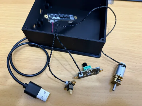
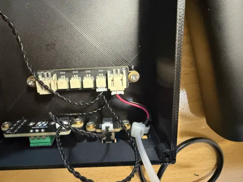
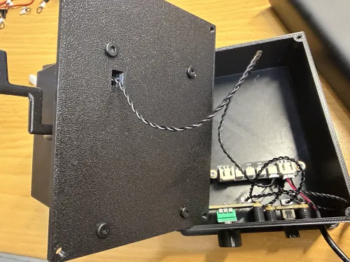
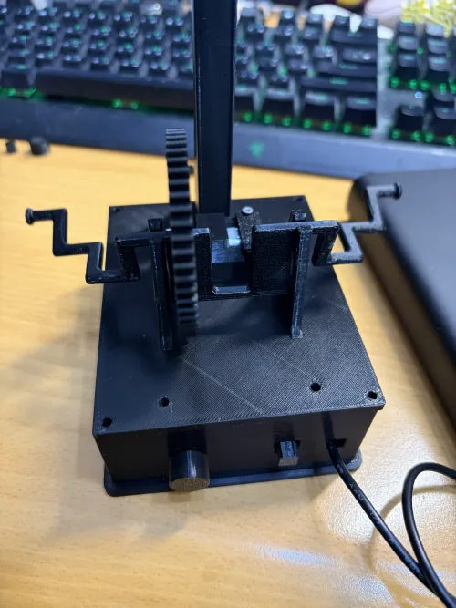
Connect components to the PDB: Power IN to USB cable; SW0/SW1 to the switch and potentiometer; CH1 to the motor. Test the speed control before securing the bottom cover with M2.5 screws.
 |
Option B: Battery Edition (Standard)
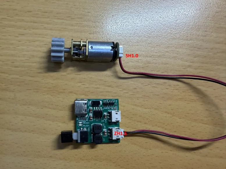
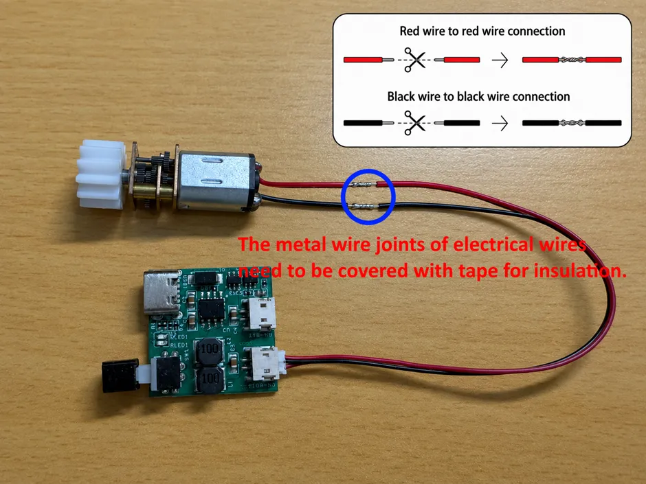
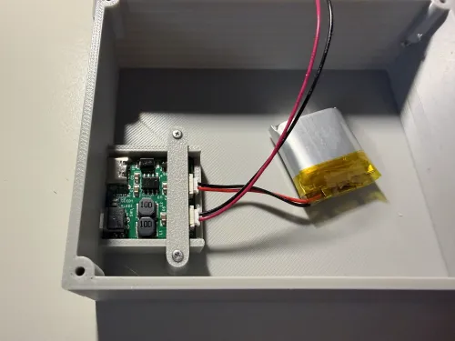
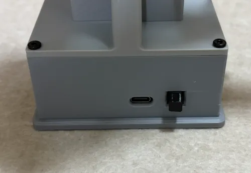
Use the 150mm conversion wire to connect the motor to the Charger Board. Use M2 screws to fix the mounting plate onto the Charger Board, and install the switch extension button. Test the movement before securing the bottom cover with M2.5 screws.
If you are using an N20 motor with an SH1.0 slot, you can use the ZH1.5 to SH1.0 wiring connection, as shown in the diagram below:
If you are using the N20 motor included with the Rechargeable Power Kit, you will need to cut off any excess connectors, as shown in the image below:
Step 4: Final Integration
Final Coupling:
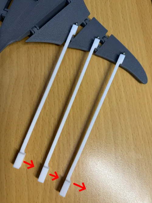
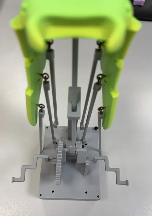
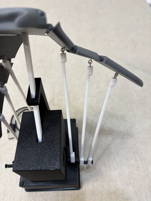
Snap the lower end of the wing rods onto the crankshaft (check the rod orientation).
Ensure the main support post is firmly inserted into the groove of the fish's body and does not wobble; if it does wobble, use adhesive to secure it.
Please carefully press the wing support into the connecting rod. Please use both hands to apply force up and down simultaneously to secure it, avoiding excessive force on one side that could break the connecting rod.Final Run:
Power on and test. For adjustable versions, fine-tune the knob to find the most graceful "sweet spot" speed.
Troubleshooting
- Movement Sticking?
- Check if the pins or screws are over-tightened. You can lightly sand the joints for smoother movement.
- Motor Noise?
- Ensure the motor is pressed firmly into its seat and check for any debris in the gears.
- Swimming Too Fast?
- Please double-check that you are using a 150rpm motor. A 500rpm motor will make the Manta Ray look like it's performing a "Panic Dance"!
Pro Tip
- Applying a small amount of grease to all ball joints and moving parts will make the motion whisper-quiet and incredibly smooth.
Documentation (1)
License

You shall not share, sub-license, sell, rent, host, transfer, or distribute in any way the digital or 3D printed versions of this object, nor any other derivative work of this object in its digital or physical format (including - but not limited to - remixes of this object, and hosting on other digital platforms). The objects may not be used without permission in any way whatsoever in which you charge money, or collect fees.


Comment & Rating (28)