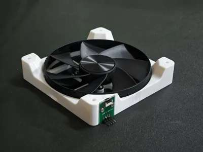
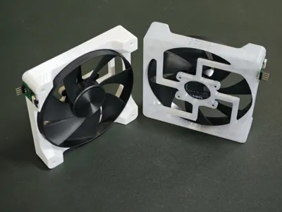
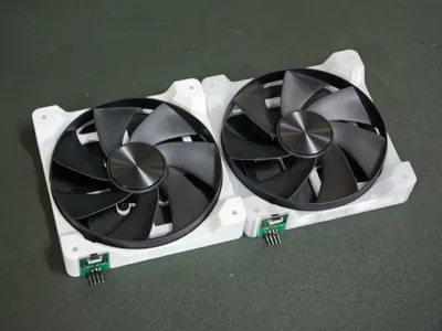
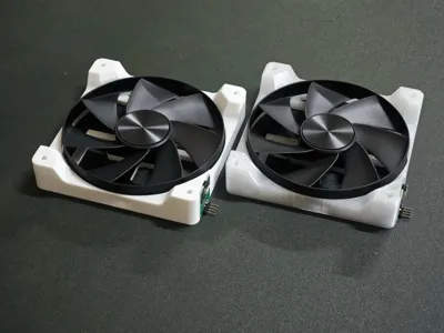
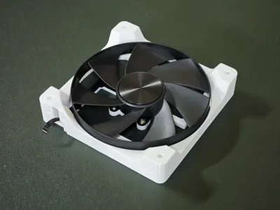
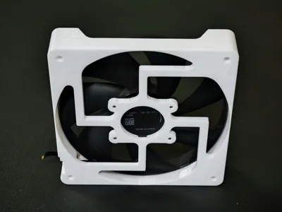
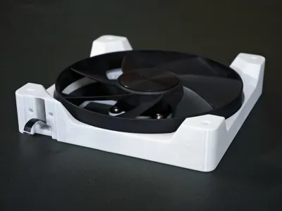
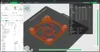
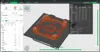
4090 fan frame for K05 FPC-8P adapter board


Print Profile(2)
Description
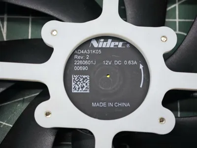
Applicable to 4090 fan AD4A31K05 (reverse blade), in conjunction with an FPC-8P adapter board
It requires 6 M2.5x6 screws (M2.5x4 x5 are also acceptable; 4 screws for fixing the fan, 2 for fixing the PCB). Self-tapping screws can be directly screwed into the corresponding holes. For a more meticulous installation, some thread locker can be applied
Actually, with a fan of the Nidec 4090's caliber, given the dynamic balance of its bearings and fan blades, there is no need to worry about vibration issues
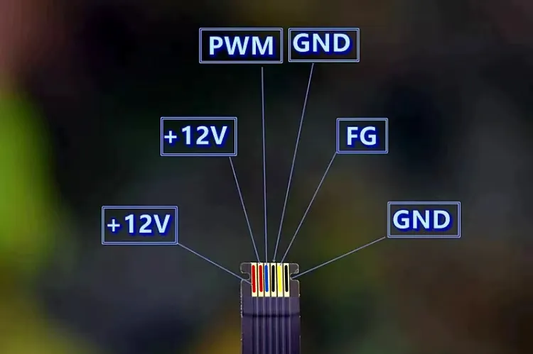
Reference wiring sequence is as follows
The fan cable is 6-pin, the adapter board is 8-pin, with the first and last pins left vacant. The output connector is a standard 2.54 connector, so you can solder a DuPont connector you have on hand
Ready-made cables are also available on the market; simply adjust the wiring sequence yourself
The wiring sequence on the motherboard, as shown in the diagram, is sequentially GND (negative, black), +12V (positive, red), FG (tachometer feedback, usually yellow, green in the diagram), PWM (PWM speed control wire, usually blue)
This wiring sequence is common on commercially available motherboards; individual OEM motherboards may require multimeter confirmation (for complete systems like Lenovo or Dell, the motherboard wiring has its own definitions)


Comment & Rating (2)