






Print Profile(1)

Description
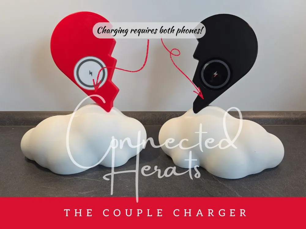
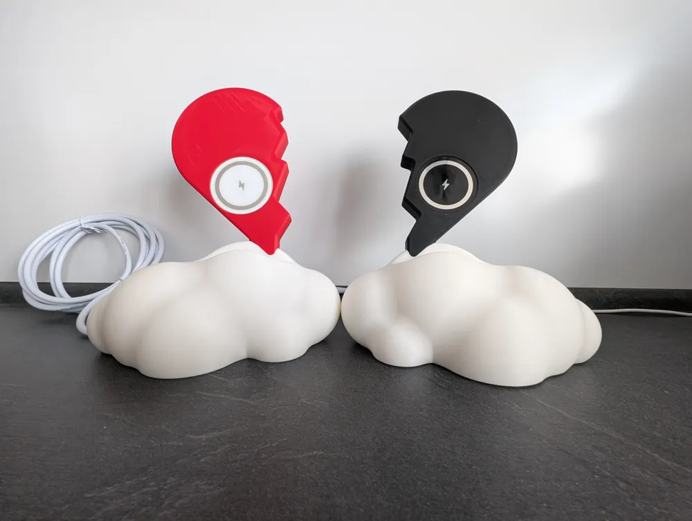
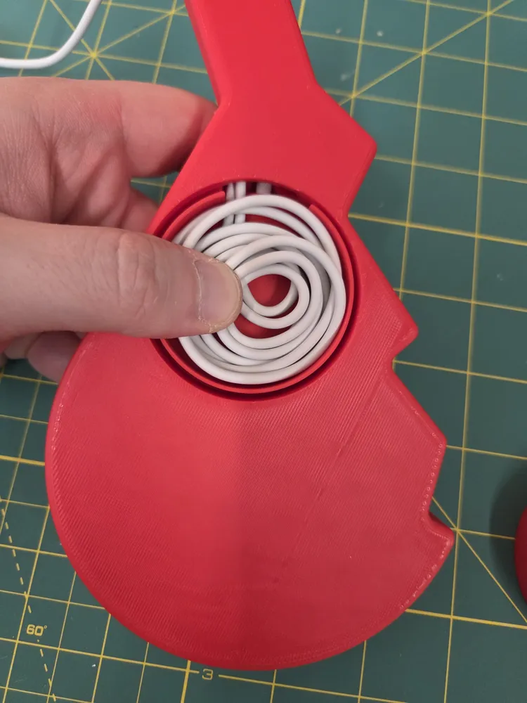
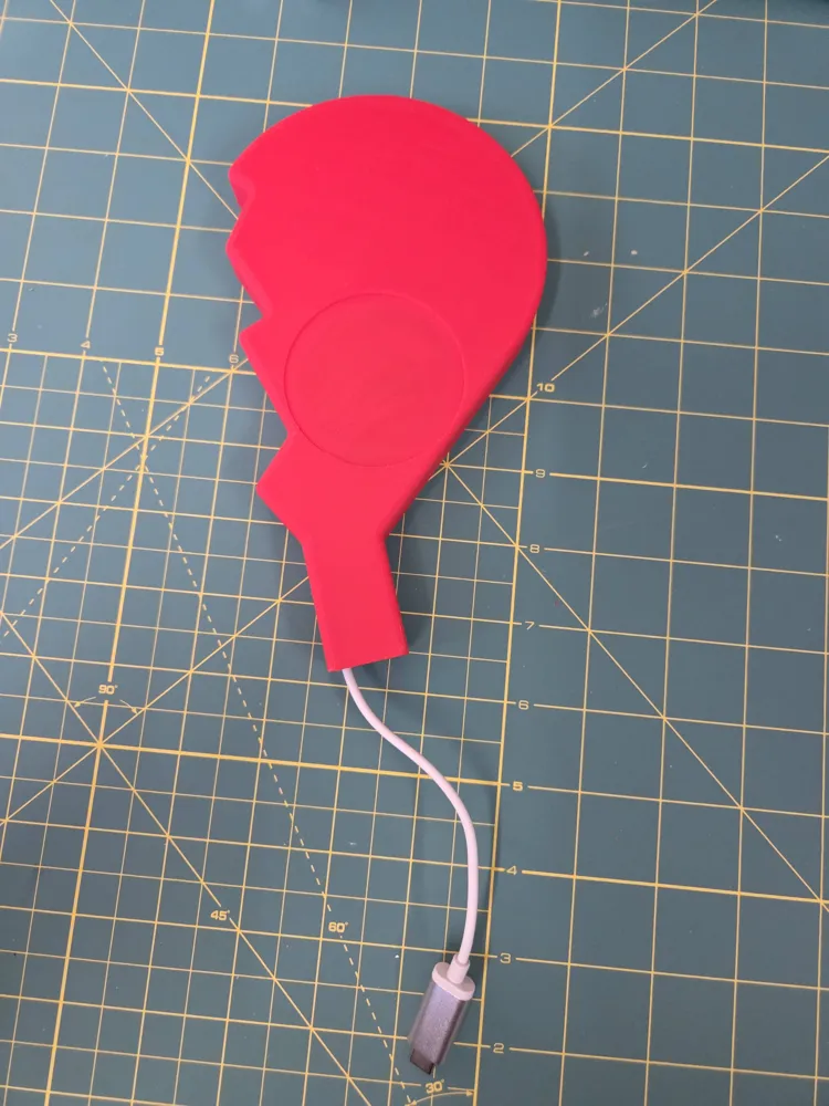
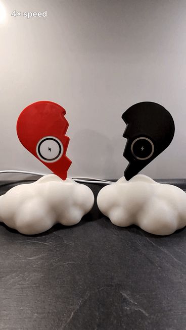
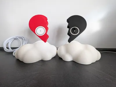
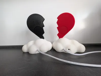
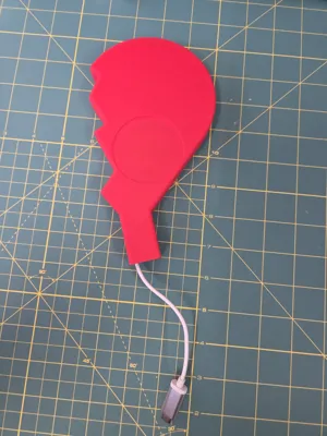
Connected Hearts is more than just another charging dock; it is a physical symbol of your connection. Designed as a pair of twin bedside stations, they operate on a fundamental principle of togetherness: "AND-Logic." Your phone only charges when your partner’s phone is also resting on its station.
It is an invitation to end the day with intention. By setting your phones down together, you shift your focus away from the digital world and toward each other. The moment both hearts are occupied, your shared time begins—undisturbed, present, and fully connected.
Key Features
- Symbol of Unity: Power only flows when both of you are "present."
- Intentional Downtime: Encourages a dedicated tech-free space to foster intimacy without the distraction of notifications.
- Mechanical Reliability: The logic is solved via robust industrial microswitches—tactile, reliable, and completely independent of buggy apps or cloud services.
- Smart Presence (Optional): Integrated NFC tags can be configured to automatically trigger "Do Not Disturb" modes or dim your smart lights. As the hearts connect, so do you.
How it Works
The system functions as a mechanical AND-gate through pure physics:
- Two separate stations, each featuring its own Qi charging pad and a mechanical microswitch.
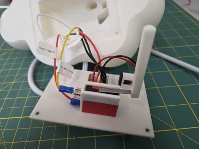
- Series Wiring: The positive (+) circuit is physically interrupted until both switches are depressed by the weight of the phones.
- The Logic: Phone on Station A or B only → No charging. Both phones placed → Both stations active.
Hardware & Preparation (BOM)
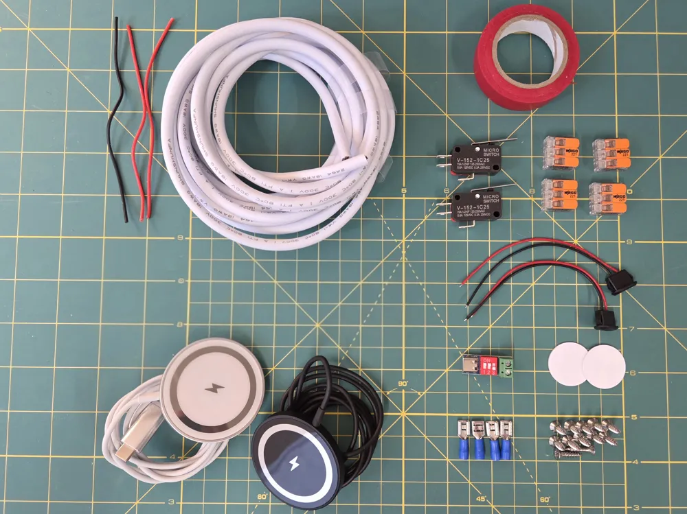
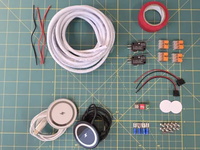
For a seamless build, I explicitly advise using the components mentioned below. The 3D-printed housing is precisely dimensioned for these specific parts:
- 2x MagSafe Wireless Chargers: For fast, magnetic alignment.
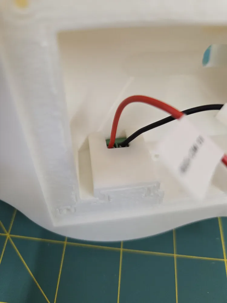
- 2x V-152-1C25 Micro Switches: Serving as the physical sensors for the phones.
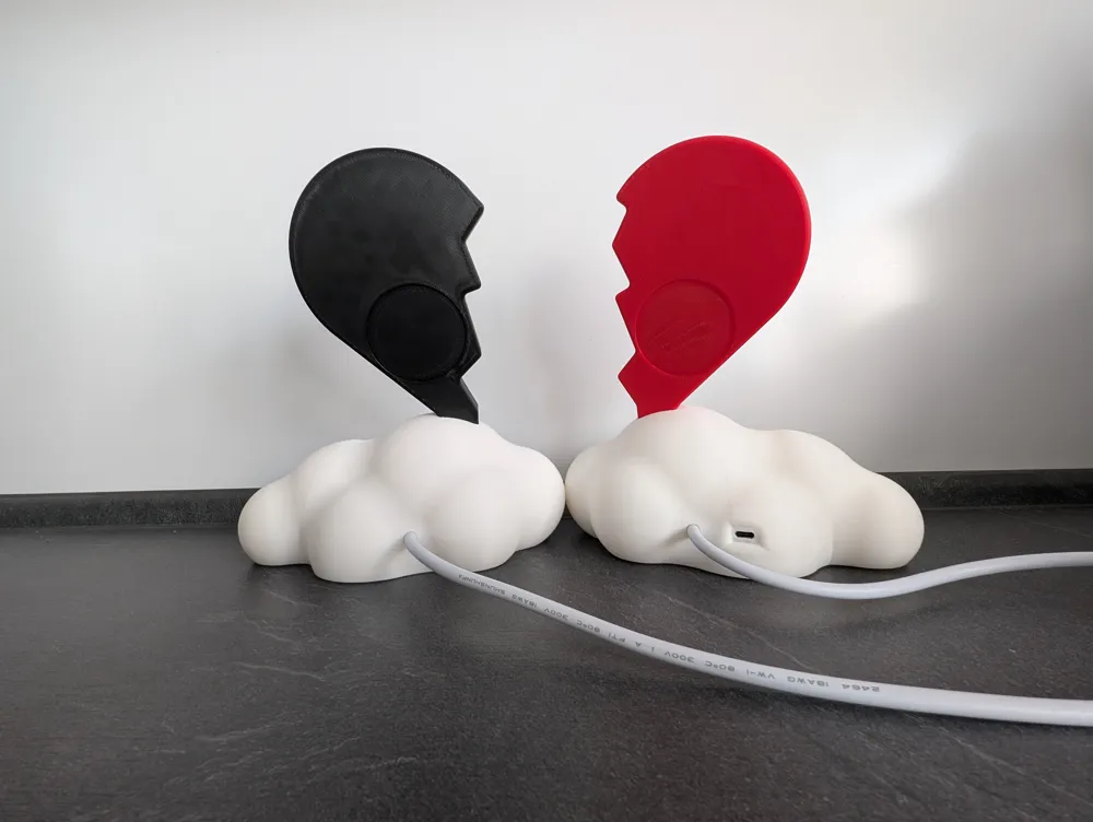
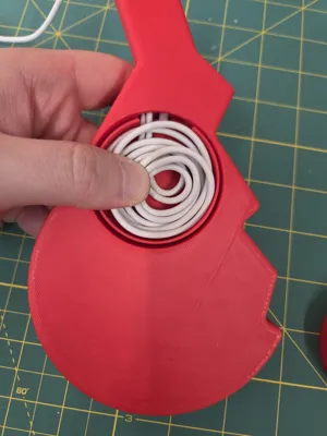
- 1x USB-C PD Trigger Board: To negotiate the required voltage from your power supply—both stations will be powered by a single charging cable (wall plug), keeping your setup clean.
- 2x USB-C Female Panel Mounts: To connect the wireless chargers internally.
- 4-core 18AWG Cable: To connect both stations (approx. 3 meters recommended).
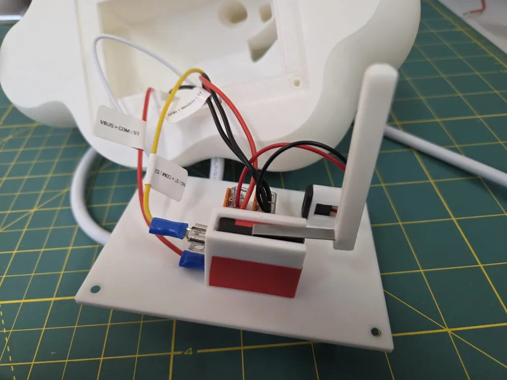
- WAGO 221-413 Splicing Connectors: For secure, solder-free wiring.
- 12x Chipboard Screws - 3.5 mm x 15 mm
- 4x Blade Terminals - Included with the micro switches mentioned above.
- 1-2x NFC Tags (Optional) - NTAG215 Stickers (540 Bytes), compatible with iOS Shortcuts and Android.
- Adhesive tape - to secure the micro switches
Required Tools: Crimping tool, screwdriver, wire stripper and side cutters.
3D Printing & Compatibility
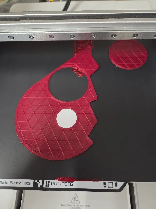
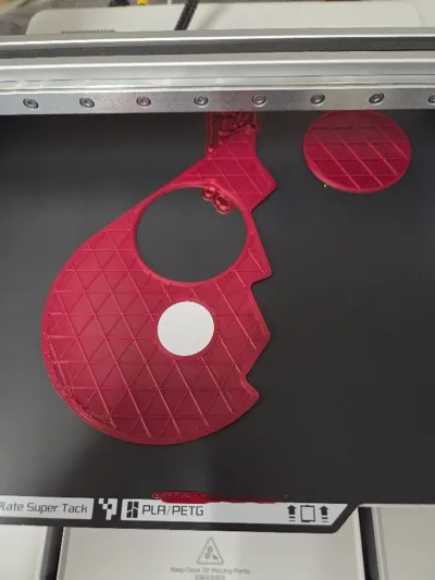
The included .3mf files are optimized for iPhone models 11 through 17 (Pro / Plus / Max) when used with a case. The Pixel 8/9 and Samsung Galaxy S25 are also compatible with the "Standard" variant.
- Customization: If your device differs, you can adjust the charger height using the Parametric Model Maker (measure the distance from the bottom of the charger to the bottom of the phone).
- Important: The base stations must always be printed from the original file as they require no adjustments. Recommended: PLA with at least 3 wall loops.
Step-by-Step Assembly
- Preparation: Cut three 10 cm individual wires (recommended: 2x Red, 1x Black) from the AWG18 cable and prepare your main connection cable (approx. 3m).
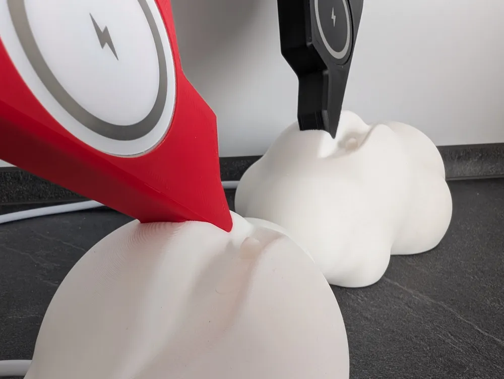
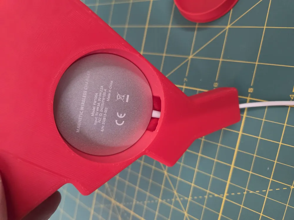
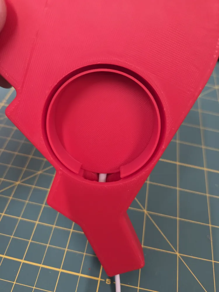
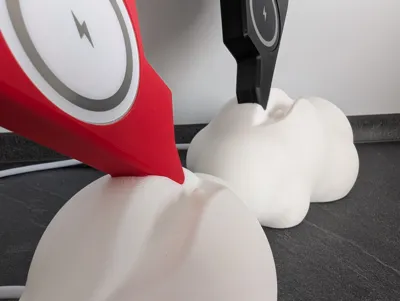
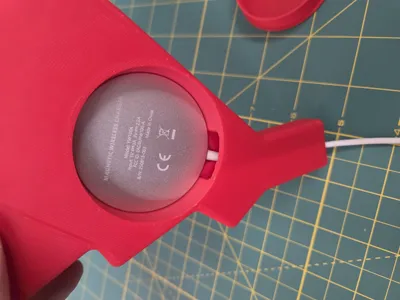
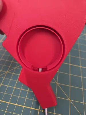
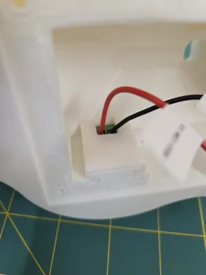
- Mechanics: Install the microswitches so the lever protrudes slightly through the guide. Thread the cable ends into the stations and secure them with the strain relief.
- The Positive Rail (+):
- Connect the Trigger Board (VBUS) to the COM port of Switch 1.
- Route a line from NO (Normally Open) of Switch 1 to COM of Switch 2 (using the yellow wire of the main cable).
- Connect NO of Switch 2 to the positive WAGO block in Station 2 and run the red wire back to the positive WAGO block in Station 1.
- The Negative Rail (-):
- Connect the Trigger Board (GND) to the negative WAGO block in Station 1.
- Connect the negative WAGO blocks of both stations using the black wire of the main cable.
- Final Touch: Connect the internal USB-C sockets to their respective WAGO blocks (+ to +, - to -) and plug in your Qi charging pads.
Why I Built This
I wanted to create a technical device that holds genuine emotional significance. By making the charging process mechanically dependent on one another, a mundane daily task is transformed into a small, shared ritual of appreciation. Connected Hearts gives you and your partner the permission to go offline and simply enjoy each other's company.
Link to Documentation / Assembly Guide: https://connected-hearts-the-couple-charger.my.canva.site/
Boost Me (for free)
I am incredibly grateful to everyone who rates this model, leaves a comment, or gives feedback. A special thank you goes out to everyone who even leaves a boost. Your support is incredibly valuable for my hobby. Thank you so, so much!
License

You may create derivative works based on this object, provided that all such derivative works are published exclusively on the MakerWorld platform and include proper attribution to the original creator. You may not share, upload, host, distribute, or publish this object—or any derivative work of this object—on any other digital platform, marketplace, or distribution channel. Commercial use of this object and any derivative works is strictly prohibited. This includes, but is not limited to, selling, renting, sublicensing, or using the object in any context in which you receive monetary compensation or other financial benefits.


Comment & Rating (1)