Search models, users, collections, and posts
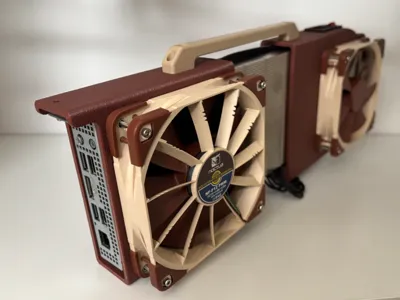
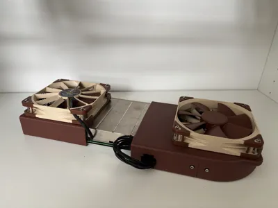
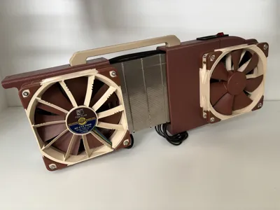
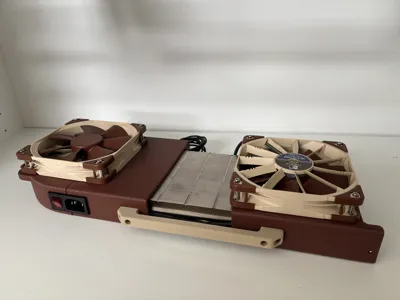
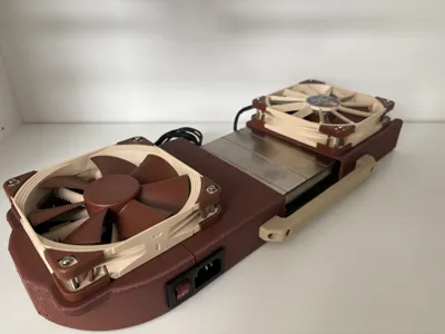
Noctua Push Pull Mod for BC-250 Shell Case
IP Report


Print Profile(1)
0.2mm layer, 2 walls, 15% infill
Designer
6.4 h
1 plate
Open in Bambu Studio
Boost
39
91
6
0
169
44
Released
Description
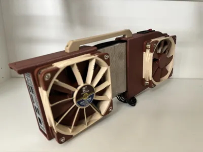
A dual-fan modification for the excellent ASRock AMD BC-250 Shell Case by onemorecap. This mod replaces the single high-RPM fan with a push-pull configuration using two Noctua NF-F12 PWM fans optimized for high static pressure - delivering some cooling at a fraction of the noise but double the price.
This is not yet fully tested but I hope it will provide quiet computing without much compromise. In theory this should work.
Disclamer: The original autor of the case does not allow for remixes, because of that I cannot add all the required model parts to this profile. To get this to work completely you need to print both this mod and parts from original case model without front part.
Before You Start
- Print the original case: ASRock AMD BC-250 Shell Case
- Leave feedback on the original — it's a fantastic design and deserves the love!
- Print the BC-250 Radiator Fin Comb (1.5 mm / 3 mm) or equivalent scooper to straighten your heatsink fins.
- Print this mod in PETG or another high-temperature-resistant filament - preferably exactly the same like the main models.
Bill of Materials
Electronics
| Qty | Part |
|---|---|
| 1× | MEAN WELL LOP-300-12 (300 W, 4″×2″, 12 V) |
| 1× | JST VH 3.96 mm — 3-pin female plug with wire |
| 1× | JST VH 3.96 mm — 6-pin female plug with wire |
| 1× | 16 AWG PSU 8-pin PCI-E (6+2) cable |
| 1× | IEC320 C14 250 V inlet connector (model AC-14-02, with mounting holes, no power switch) |
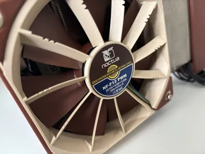
| 2× | Noctua NF-F12 PWM (12 V) (I managed to get a set of 3 such fans from local marketplace, strongly recommend.) |
| 1× | PWM fan Y-splitter |
| 1× | PWM extension cable (≥ 10 cm) |
Hardware
| Qty | Part |
|---|---|
| 20× | M3 heated inserts (M3×3×5 or M3×4×5) |
| 16× | M3×6 ISO 7380-1 (button head) |
| 7× | M3×10 ISO 7380-1 (button head) |
| 10x | JST VHR crimp terminals (0.3–0.8 mm²) |
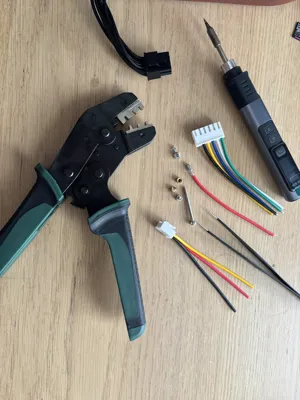
Tools
| Tool | Notes |
|---|---|
| Soldering iron | Required - for setting heated inserts and soldering the AC connector |
| Fine-tip pliers | To open JST connector housings for re-pinning |
| Connector crimping tool | For JST VHR crimp terminals (0.3–0.8 mm²) |
Assembly Guide
Print & Prep
- Print the original case, this mod, and the fin comb/scooper.
- Leave nice feedback to the original creator of the case - without him it would not be possible!
- Press all 20 heated inserts into place using a soldering iron.
Wiring the PSU Cable
- Using fine-tip pliers, remove the pins from the 6 pin connector so you can re-pin them into the JST connectors after you cut the PCIE cable just before PSU end.
- If you have a standard 6+2 PCI-E cable, wire it as follows:
- 6-pin JST connector → PSU: The bottom three wires (yellow on the picture below) on the 6-pin PCI-E side are +12 V (same in case of 6+2). Connect these to PSU pins 1, 2, 3 (top row, with connectors facing right). The remaining five ground wires connect to PSU pins 4, 5, 6

- AC inlet: Solder the 3-pin JST connector wires to the IEC320 C14 inlet.
Final Assembly
- Connect the PWM Y-splitter to the motherboard's fan header.
- Attach the PWM extension cable to one leg of the Y-splitter (this reaches the second fan).
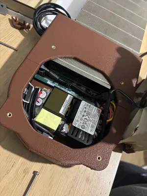
- Route all cables, squeeze everything into the case, and start screwing it together.
- Use the Scooper/Comb to open a heatsink fins when the fan holes are - once this is done removal of the case is almost impossible. Make sure you have installed NVME drive by this point.
- Good luck - it's a tight fit! 😄
Filament colors: PETG Pantone 483, Bone PLA.
License
This user content is licensed under a
Creative Commons Attribution-Noncommercial-Share Alike
Comment & Rating (6)