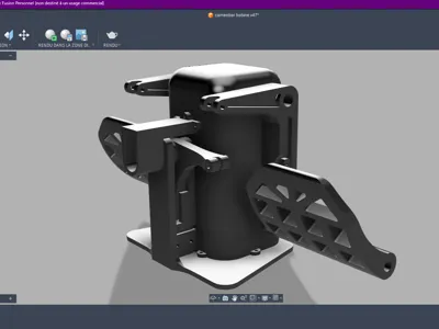
Rudder pad type pendular rudder


Print Profile(1)
Description
Pendular rudder pedal (I was inspired by it, but it's not a strict copy of the Thrustmaster)
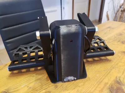
I designed this rudder pedal for my simulation chair, so it mounts on a rigid support
It replaces my old Saitek, which was too heavy, too big, and after 4 years, it was malfunctioning (Saitek's potentiometers are truly poor quality; I had the same issue with their yoke)
The advantage here is that although the potentiometers are rated for 10,000 rotations, you can easily replace them
This rudder is simple to assemble and requires minimal hardware (approximately 30 euros investment; it cost me less because I already had diodes, wires, metal rods, and RC-type arms)
It prints in 2 days and assembles in 1 morning
You will need a 10 mm and an 8 mm rod, to be cut to the following dimensions: 10 mm rod - 14 cm 8 mm rod - 13 cm (2 rods)
Bolts are not necessary
Two RC car-type articulated rods: 3 to 6 cm adjustable, it's up to you (approximately 20 €)

One Arduino Micro board (important for USB HID) (4 €) from AliExpress
Three 1K potentiometers (3 €) (see photo for potentiometer type)

One red LED diode (20 cents)
One 220 ohm resistor (20 cents)
Two 2 cm springs with hooks (3 €)

The code for the Arduino:
#include <Joystick.h>
Joystick_ Joystick(JOYSTICK_DEFAULT_REPORT_ID,
JOYSTICK_TYPE_JOYSTICK, 0, 0,
true, true, true,
false, false, false,
false, false, false,
false
);
const int potX = A0;
const int potY = A1;
const int potZ = A2;
const int ledRouge = 10;
int readSmooth(int pin) {
const int samples = 5;
long total = 0;
for (int i = 0; i < samples; i++) {
total += analogRead(pin);
delayMicroseconds(5);
}
return total / samples;
}
int applyDeadzone(int value, int center, int deadzone) {
if (abs(value - center) < deadzone) return center;
return value;
}
void setup() {
pinMode(ledRouge, OUTPUT);
digitalWrite(ledRouge, HIGH);
Joystick.begin();
Joystick.setXAxisRange(0, 1023);
Joystick.setYAxisRange(0, 1023);
Joystick.setZAxisRange(0, 1023);
}
void loop() {
int xValue = readSmooth(potX);
int yValue = readSmooth(potY);
int zValue = readSmooth(potZ);
xValue = applyDeadzone(xValue, 512, 6);
yValue = applyDeadzone(yValue, 512, 6);
zValue = applyDeadzone(zValue, 512, 6);
Joystick.setXAxis(xValue);
Joystick.setYAxis(yValue);
Joystick.setZAxis(zValue);
delay(10);
}
Warning: you will need to install the MHeironimus joystick library for Arduino, available online here:
https://github.com/MHeironimus/ArduinoJoystickLibrary
For the rear axis, a simple, slightly thick elastic band can be wrapped multiple times if necessary to create tension. Holes are pre-drilled, so if you wish to improve the design and add springs, that's possible
The Arduino assembly diagram is simple:
A0, A1, and A2: Solder to the middle pin of the three potentiometers (A0 potentiometer 1, etc.)
GND: Connect all GNDs of the three potentiometers and the red diode
VCC: Connect the three positive terminals of the potentiometers to VCC (5V)
Pin 10: 220 ohm resistor, connected to the anode of the red diode (long lead)
The code is designed to prevent potentiometer "jitter", making it a precise rudder pedal (with an adjustable dead zone in the code)
You will need to attach it to a board or support to use it
The rudder pedal that inspired me costs 550 €, weighs 7 kg, and the link is here: https://flightsimzone.com/fr/products/tpr-thrustmaster-pendular-rudder-a-vendre
And finally, more detailed photos of the rudder for assembly:


For print profiles, to save time, print with a 0.2 mm layer height
Four parts must be printed with 100% infill; this should be correctly configured in the 3mf profile, but please verify: the axle for the pedal rocking, the rear potentiometer cover, and the two articulation tabs for the front potentiometers
And finally, a video of the completed and functional project:
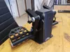
P.S. I'm adding a photo of the rear assembly, as some had difficulty understanding how to put it together

Comment & Rating (0)