
SATA Cartridge Bay 2.5 Passive
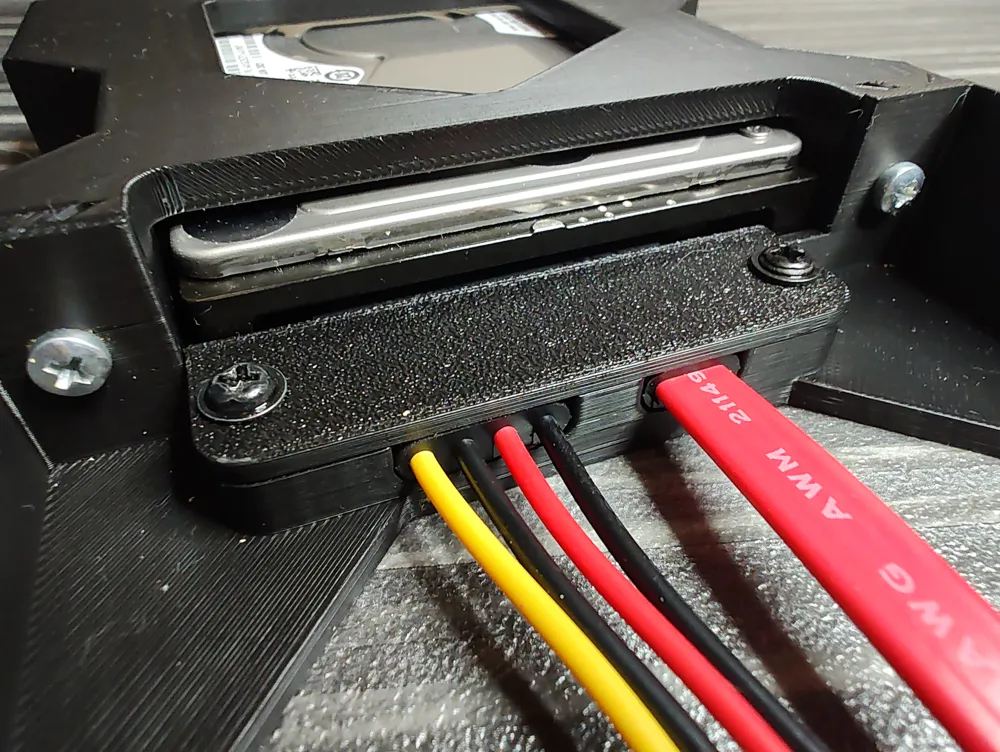
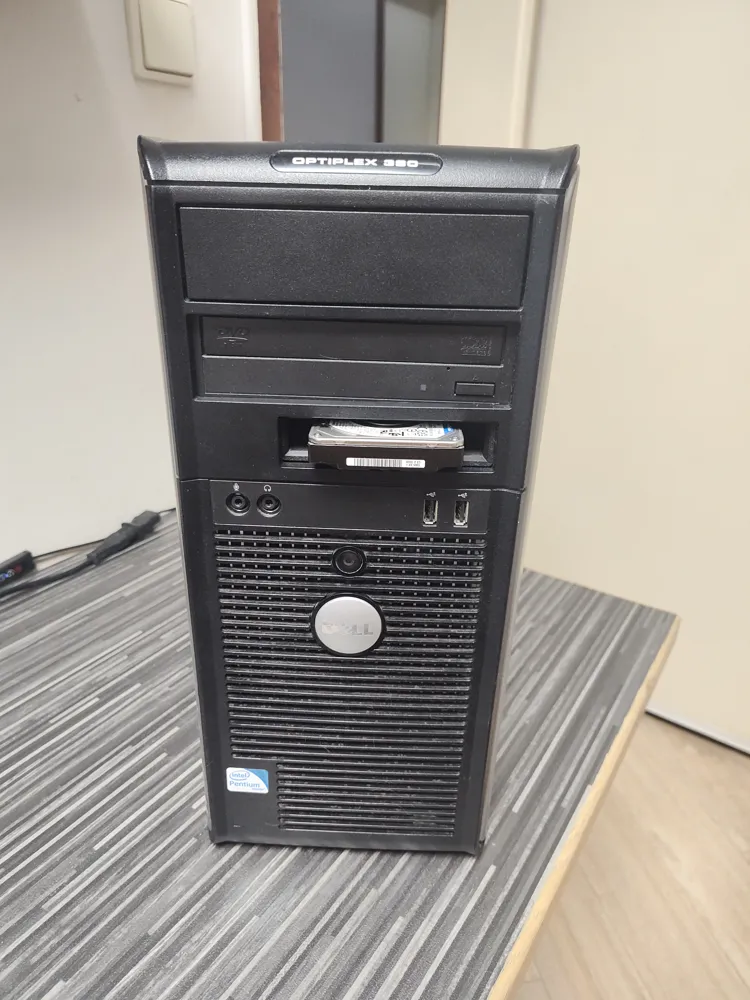
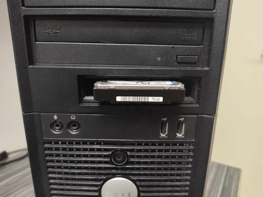
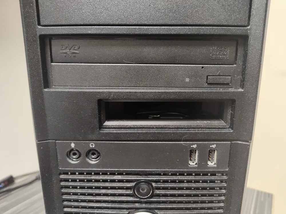
Print Profile(1)
Bill of Materials


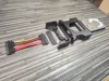
- Combined SATA Connector x 1: https://www.aliexpress.com/item/1005008747395106.html
Description
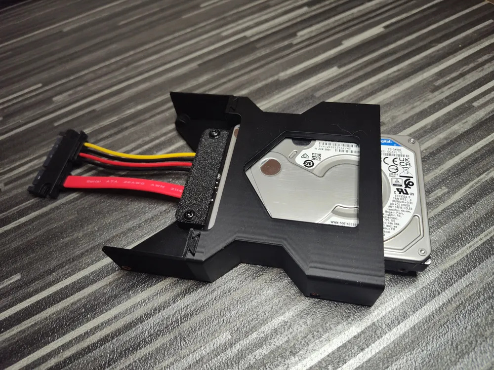
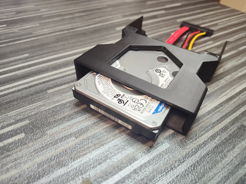
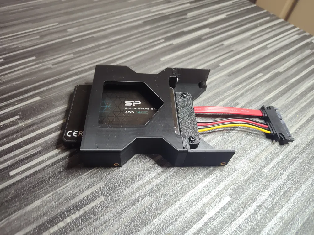
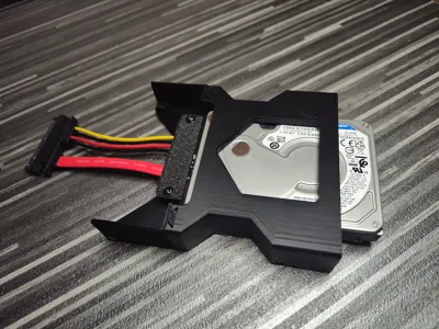
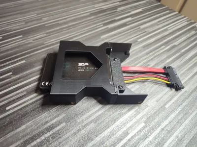
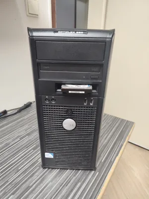
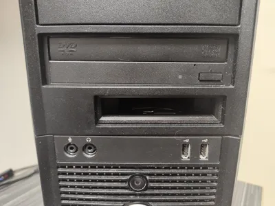
This model is an adapter for installing a 2.5” SATA drive into a standard 3.5” floppy bay. The idea is simple – to use the floppy bay as a space for the drive, without any prior modifications or attachments to the drive itself (screws, frames, handles).
This model is part of SATA Cartridge Bay series:
- SATA Cartridge Bay 2.5 Passive (this model)
- SATA Cartridge Bay 2.5 (eject button)
- SATA Cartridge Bay 3.5 (eject button)
Model Parts
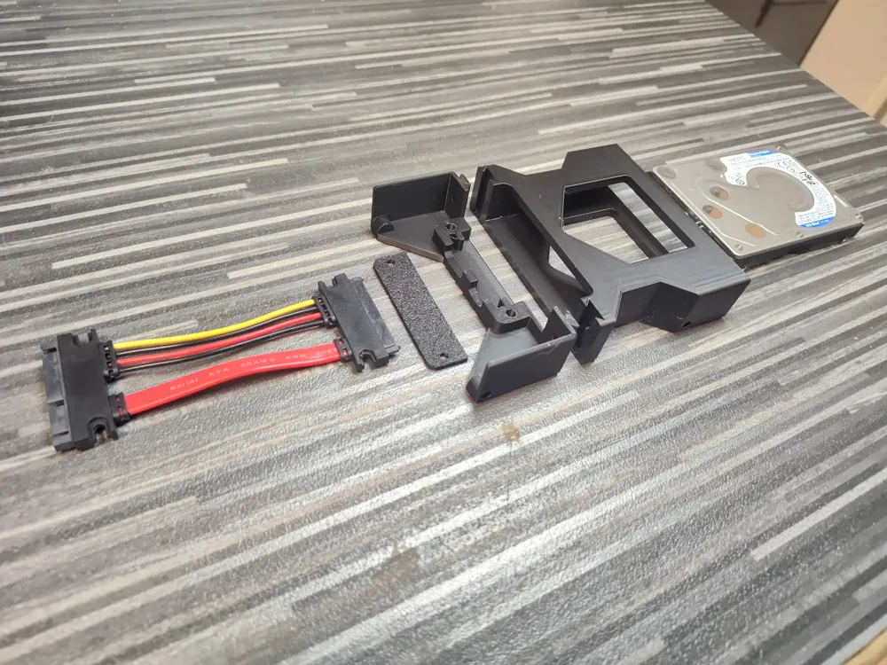
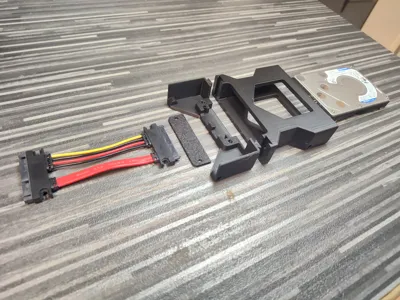
The model consists of two main parts – front and back. The back part slides onto the front through specially designed channels, and the two parts are then secured with screws. This creates a stable assembly without play, while remaining easy to assemble and disassemble.
SATA Connector
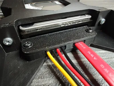
The back part includes a slot for a combined SATA connector (data + power). The connector is placed on top and secured with a cover, which is also fastened with screws.
The model is specifically designed for use with this type of SATA connector, with the geometry of the back part precisely matching its dimensions and position. This ensures correct alignment of the drive and a secure connection without stress on the connector.
Nuts and Screws
A total of 8 M3 embedded nuts with a depth of up to 8 mm are required for assembly.
Four are for the front part – two for mounting to the chassis and two for connecting to the back part.
The other four are for the back part – two for mounting to the chassis and two for the SATA connector cover.
The nuts used to connect the front and back parts are placed inside the channels where the two parts slide into each other. Installing them with a soldering iron requires care, as there is a risk of melting the material in the channel. For easier and safer assembly, it is recommended to place these nuts with a pre-inserted longer screw (about 15–20 mm), which can be pressed with a soldering iron.
The screws connecting the front and back parts should be longer (at least 8 mm) than standard M3 PC case screws, which are used for mounting to the chassis and the connector cover.
How to Use
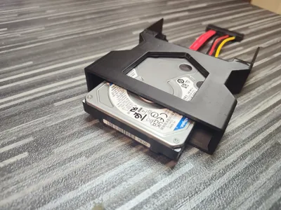
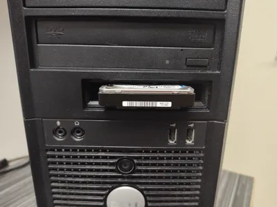
The drive sticks out slightly at the front, making it easy to grab and remove by hand without tools or additional mechanisms. This is intentional, as a flly recessed drive would be harder to remove. It is recommended to remove the drive only once it has been safely unmounted by the operating system.
In the current version, the model is made entirely from rigid material, focusing on simplicity, durability, and functionality. Minor scratches from inserting and removing the drive are not critical, and in the future, a softening insert could be added if needed.
License

You may create derivative works based on this object, provided that all such derivative works are published exclusively on the MakerWorld platform and include proper attribution to the original creator. You may not share, upload, host, distribute, or publish this object—or any derivative work of this object—on any other digital platform, marketplace, or distribution channel. Commercial use of this object and any derivative works is strictly prohibited. This includes, but is not limited to, selling, renting, sublicensing, or using the object in any context in which you receive monetary compensation or other financial benefits.


Comment & Rating (0)