UNIVERSAL SOLDERING JIG

Print Profile(2)
Description
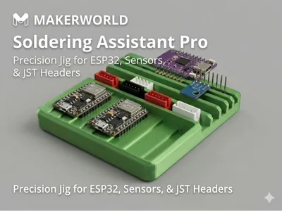
The Soldering Assistant Pro: Precision Jig for Headers & Sensors
If you have ever struggled to keep female headers straight or fought with JST connectors that won't stay flat on a PCB while soldering, this tool is for you. While breadboards work for male headers, they are often a hassle for everything else. This soldering platform is a dedicated "third hand" for your workbench, designed to ensure perfect alignment every time.
The Problem it Solves
Most soldering jigs are either too generic or too clunky. When soldering female headers, they often tilt or fall out because they lack the friction of a breadboard. Similarly, JST connectors and different-sized sensors (like buzzers) never sit at the same height as your PCB, leading to messy, crooked joints.
Key Engineering Features
- Universal Header Support: Precision-cut slots to hold Female and Male pin headers perfectly perpendicular to your PCB.
- JST 2.54mm Dual Support: Dedicated slots for both vertical and horizontal JST connectors, keeping them locked in place while you apply solder.
- 1mm Cascading Stair Profile: The unique "staircase" design features 1mm height increments. This allows you to rest sensors of varying thicknesses (from thin OLEDs to thick buzzers) on the steps so they sit perfectly flush with your board.
- Integrated Storage Tray: The stair profile doubles as an organization tray to keep your components ready and sorted before you begin your build.
Print Settings (Optimized for Bambu Lab A1)
- Material: PLA works fine if you are careful!
- Layer Height: 0.2mm (to ensure the 1mm steps are accurate).
- Walls: 3 walls for structural rigidity.
- Infill: 15% (Gyroid).
- Support: Not required.
How to Use
- Insert your headers or JST connectors into the designated slots.
- Place your PCB over the pins.
- If using a sensor of a different height, slide it along the 1mm steps until it supports the component perfectly flat against the PCB.
- Solder with confidence!
I’d love to see your builds! If this helps your workflow, please leave a rating or a comment with your latest project.
License
You shall not share, sub-license, sell, rent, host, transfer, or distribute in any way the digital or 3D printed versions of this object, nor any other derivative work of this object in its digital or physical format (including - but not limited to - remixes of this object, and hosting on other digital platforms). The objects may not be used without permission in any way whatsoever in which you charge money, or collect fees.
Comment & Rating (31)