Stop valve with switch / Shut-off valve


Print Profile(8)


Description
Description
German | English |
|
|
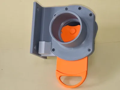
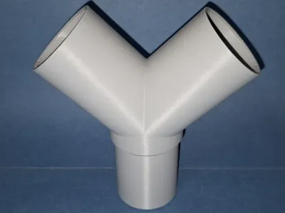
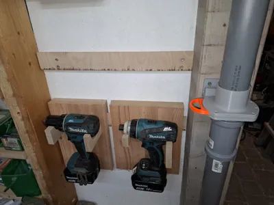
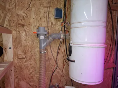
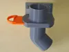
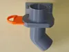
A friend built an extraction system for his enviable woodworking workshop, to which all suitable devices were to be connected. He used the inexpensive HT50 pipe system for this purpose.
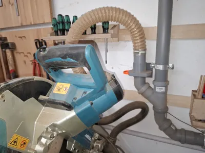
- Each device was to be equipped with its own shut-off valve.
- Activating a shut-off valve was to immediately activate the extraction system.
- To activate the extraction system, all that was needed was to close a contact. This is done in the low-voltage range with a barely measurable current flow.
- Since he couldn't find any ready-made parts, he turned to me.
- Unfortunately, my search for ready-to-use shut-off valves was unsuccessful due to the required characteristics:
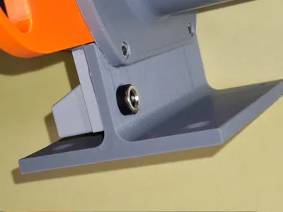
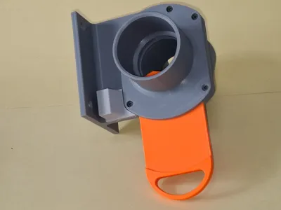
- HT50 (slide onto the device hose in front of the shut-off valve, connect directly to the pipe system behind the shut-off valve).
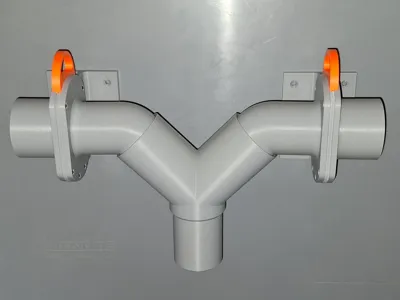
- The connection behind the shut-off valve must be angled at 45 degrees.
Both the angled pipe and the direction of the gate valve should point to the left and right. - Wall bracket
- Electrical switching function to control the extraction system.
- As a source of inspiration, I used model 4809158 by Stevetecx from Thingiverse.
- My idea was to create a remix with all the required features on this basis.
- The most difficult part was the electrical function.
- I decided against a mechanical solution, not least because of the dusty environment and durability issues.
- A reed relay was embedded in the glass body within the frame.
- I used two neodymium magnets in the pusher.
- A 2-pin socket was then installed in the frame and covered with a cap (glued on).
- All plugs that are inserted into the 2-pin socket are connected in parallel. Regardless of which shut-off slide is activated, the extraction system starts up.
- Please note that I have not remained compatible with the base of the Remix in terms of the arrangement of the screw holes. This means that the individual parts are not interchangeable.
In practice, it has been shown that the shut-off slides are so tight when simply plugged into each other that no seals are required.
- Assembly
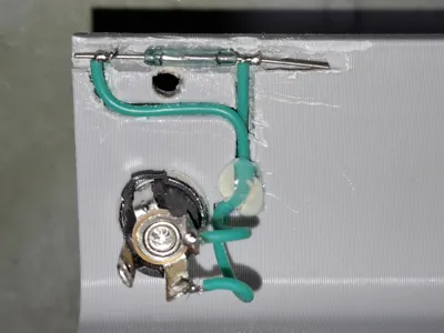
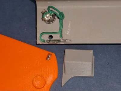
- There are a few things to keep in mind when installing the reed switch.
- Do not try to bend the connecting wires. Cutting with side cutters is acceptable. This will result in a high rate of rejection due to broken glass bodies.
- Carefully wrap the wires with highly flexible stranded wire and solder them in place.
- Then fix the reed switch in the designated position.
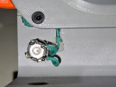
- Feed the cables through the prepared channels and secure with a drop of hot glue. These will be covered after assembly.
- Ensure that the cables are routed appropriately at the socket, as otherwise there may be problems with the protective cap.
- I attached the protective cap with hot glue, but most other adhesives will also work.
The two 3x3mm neodymium magnets should be glued into the pusher.
- There are a few things to keep in mind when installing the reed switch.
- Function test
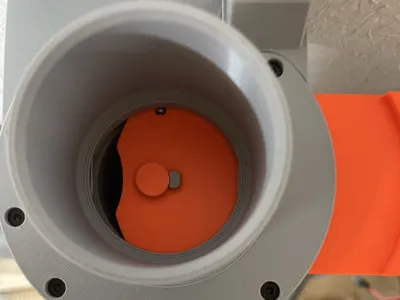
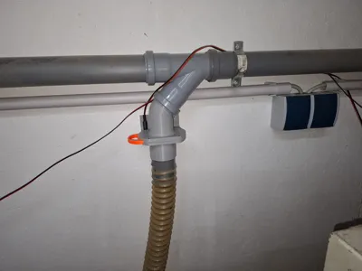
- When pulling out the pusher, the switch should be activated by the magnet glued into the pusher.
- The switch must remain switched on even when the pusher is pulled all the way out.
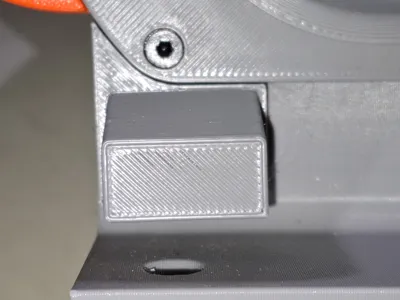
- If the switch switches off again at the last moment, the reed switch has been set too far in.
- In this case, instead of repositioning the reed switch, you can glue a small blocker in front of the slide stop (see photo).
Since the thickness of the blocker depends on the offset of the reed switch, I have added the blocker in different thicknesses to the list of stl files (1.5, 2.0, 2.5, 3.0, 3.5, and 4.0 mm).
- Material
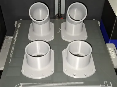
- Printing in PETG or ASA possible.
- My favorite is: everything in gray PETG, pusher in red ASA (because of the great intense color of Extrudr Durapro ASA).
- Small parts:
- Print profile
Up: straight, down: straight, pusher left Up: straight, down: straight, pusher left 

Up: straight, down: straight, pusher right Up: straight, down: straight, pusher right 

Up: straight, down: left, pusher left Up: straight, down: left, pusher left 

Up: straight, down: left, pusher right Up: straight, down: left, pusher right 

Up: straight, down: right, pusher left Up: straight, down: right, pusher left 

This remix is based on

License
You may create derivative works based on this object, provided that all such derivative works are published exclusively on the MakerWorld platform and include proper attribution to the original creator. You may not share, upload, host, distribute, or publish this object—or any derivative work of this object—on any other digital platform, marketplace, or distribution channel. Commercial use of this object and any derivative works is strictly prohibited. This includes, but is not limited to, selling, renting, sublicensing, or using the object in any context in which you receive monetary compensation or other financial benefits.
Comment & Rating (1)