Speeduino v0.4.3d ECU Enclosure


Print Profile(1)
Bill of Materials


Description
Description
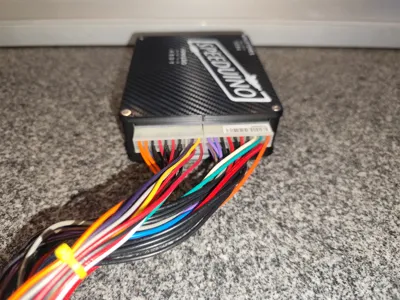
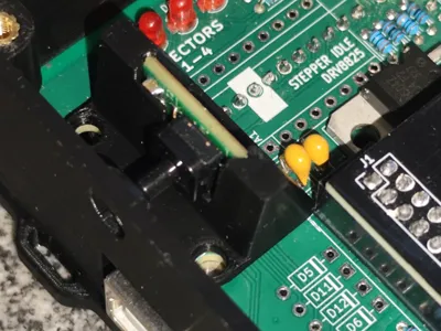
This is a dedicated enclosure for the Speeduino v0.4.3d board, designed for use in an automotive environment.
The enclosure is designed to work with an adapter board (made by me) that converts the Speeduino connections from the IDC40, to two 5569 (2×10 pin) connectors, commonly used in PC hardware power cabling/connectors.
What’s included
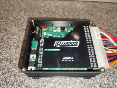
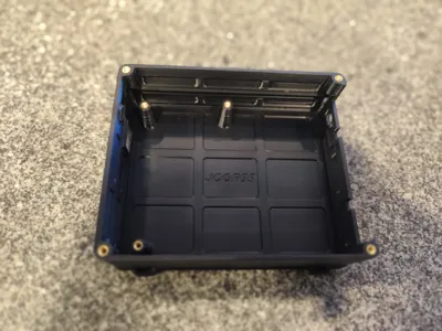
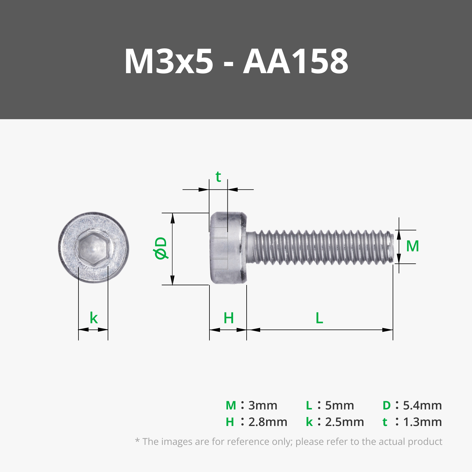
- Base (main body): mounting for the Speeduino using 3 fastening points, with M3 brass heat inserts.
- Lid: attaches to the base with 4 M3 screws, also using M3 brass heat inserts.
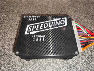
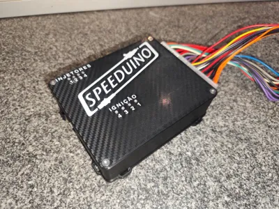
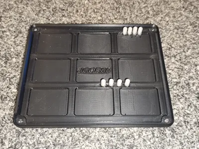
- Two-colour lid details: “Speeduino” logo (ideal for AMS or a manual filament swap).
- LED holes: 8 holes (4 ignition + 4 injector).
- 8 translucent parts (“windows”/light guides) to fit into the lid and improve LED visibility when lit.
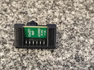
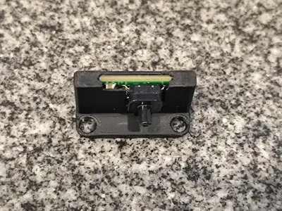
- MAP board mounting part (additional support/holder included in the project).
Functional details
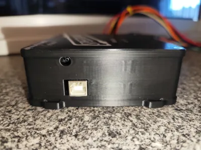
- Side A: opening for the MAP sensor hose and access to the Arduino Mega USB-B port.
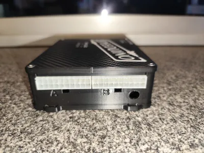
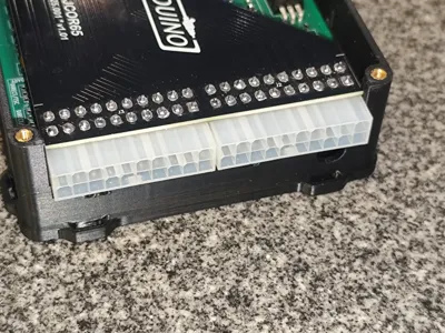
- Side B: recess to accommodate the 5569 2×10 connectors.
━━━━━━━━━━━━━━━━━━━━━━━━━━━━━━━━━━━━━━━━━━━━━━
Description
This is a dedicated enclosure for the Speeduino v0.4.3d board, designed for use in an automotive environment.
The enclosure is designed to work with an adapter board (made by me) that converts the Speeduino connections from the IDC40 connector to two 5569 (2×10 pin) connectors, commonly used in PC hardware power cabling/connectors.
What’s included
- Base (main body): mounting for the Speeduino using 3 fastening points with M3 brass heat inserts.
- Lid: attaches to the base with 4 M3 screws, also using M3 brass heat inserts.
- Two-colour lid details: “Speeduino” logo (ideal for AMS or a manual filament swap).
- LED holes: 8 holes (4 ignition + 4 injector).
- 8 translucent parts (“windows”/light guides) to fit into the lid and improve LED visibility when lit.
- MAP board mounting part (additional support/holder included in the project).
Functional details
- Side A: opening for the MAP sensor hose and access to the Arduino Mega USB-B port.
- Side B: recess to accommodate the 5569 2×10 connectors.
Boost Me (for free)
🚀 Like this project? Tap Boost Me to show your support 💙 and help others discover it too. Thanks for being part of the maker community! 🙌
License
You shall not share, sub-license, sell, rent, host, transfer, or distribute in any way the digital or 3D printed versions of this object, nor any other derivative work of this object in its digital or physical format (including - but not limited to - remixes of this object, and hosting on other digital platforms). The objects may not be used without permission in any way whatsoever in which you charge money, or collect fees.
Comment & Rating (1)