Triton router plate


Print Profile(0)
Description
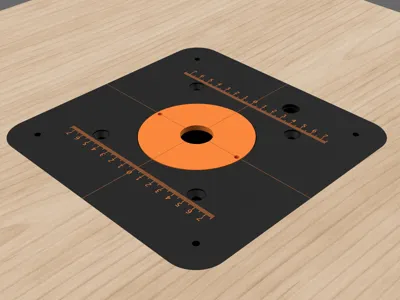
This project is a **3D Printed router table plate**, designed for the installation of a benchtop router (e.g. Triton MOF001 or compatible models), engineered to ensure **rigidity, flatness, and fine level adjustment**. The plate has a hole that allows for milling height adjustment with the specific Triton adjustment rod
The plate is conceived as a **modular system**, with dedicated accessories that simplify its installation, adjustment, and long-term use
Due to the maximum printing dimensions of the Bambu Lab P1S, the plate (and consequently the recess in the workbench) cannot be made large enough to allow the router to pass through the recess itself
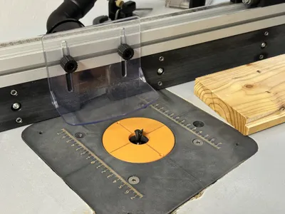
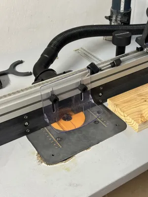
For this reason, the router is installed **from the underside of the workbench** and attached to the plate **once the latter is already mounted and leveled on the table**
**NOTE: the published print profile has been removed because the measurements provided by Triton for the distance between the plate's router mounting holes are incorrect. 102mm and 4 1/16" are indicated, the correct measurement is the imperial system one which actually corresponds to 103.19mm. This difference does not allow for precise mounting without enlarging the holes after printing the plate. I have solved the problem and am proceeding to reprint it, currently I have tested a sample to validate the distance and it is now resolved.**
Components included in the project
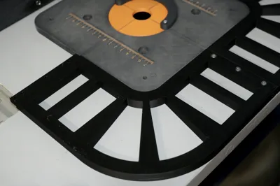
1. Main Plate
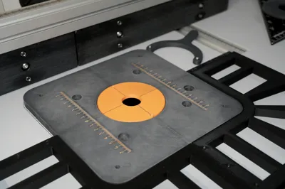
Structural plate **10 mm** thick, designed to be recessed into the workbench
Dimensions: **216 mm × 216 mm**
The geometry and fixing points are designed to transfer the router's weight to the corners, minimizing flex over time
The plate can include **metric references (rulers)** printed directly on the surface to facilitate adjustments (AMS required)
2. Corner Leveling Supports (x4)
Supports to be mounted under the workbench, corresponding to the corners of the plate
Each support:
- accommodates an **M4 threaded insert**
- allows for **fine level adjustment via screw from above**
- creates a **rigid support**
- must be fixed to the workbench with two 3mm diameter self-tapping wood screws
This solution allows the plate to be leveled precisely, without directly modifying the workbench
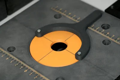
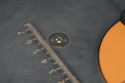
3. Interchangeable Central Insert for Router Bit Passage
Insert screwable to the main plate, with a **1" central hole** for the router bit passage
The project includes the possibility of creating **alternative inserts with different diameters**, in order to:
- minimize clearance around the router bit
- improve workpiece support
- increase safety and precision
The inserts can be replaced quickly without disassembling the plate from the table
4. Mounting Key for Central Insert
Dedicated key for screwing and unscrewing the central insert simply and securely, without damaging the plate surface
The key's thickness is designed for the use of two **M2** threaded inserts, into which two screws are inserted to act as "teeth" for engaging the central insert
5. Corner Template for Creating the Workbench Recess
Modular template composed of **4 corner elements**, designed to facilitate the creation of the recess in the workbench
It is ideal for milling or finishing the hole precisely and controllably
Features:
- The 4 elements can be nested together
- Each side is secured with **3 M3×10 screws**
The template ensures:
- correct dimensions
- repeatability of results
Recommended Print Settings
The **provided 3MF file already includes all recommended print settings** to ensure mechanical strength, rigidity, and long-term stability of the plate and its accessories
The settings in the 3MF are specifically optimized for:
- the structural rigidity of the main plate
- the correct load distribution on the leveling supports
- resistance in critical areas (countersunk screw seats and threaded insert housings)
To achieve the best results, it is recommended to:
- use the 3MF file without modifying infill, number of walls, or print orientation
- print with rigid materials suitable for structural parts (e.g. PLA-CF, PETG-CF, PA-CF)
- install the threaded inserts appropriately based on the material used
It is possible to modify purely aesthetic parameters, but it is **not recommended to alter structural settings**, as the project relies on the provided configuration to achieve the intended mechanical performance
Required Hardware
For the assembly and installation of the plate and its accessories, the following hardware components are required:
Plate and Leveling Supports
- 4 M4 threaded inserts (for the corner leveling supports)
- 4 M4 screws for level adjustment (length according to workbench thickness)
- 4 ¼-20x3/4" screws with flat countersunk head for attaching the router to the plate
- 8 screws for fixing the supports to the table, 3mm hole diameter (type and length based on table material)
Central Insert
- 2 M2 threaded inserts for the mounting key
- 2 M2x15mm screws to be used as "teeth" for engaging the key
Corner Template
- 12 M3×10mm screws (3 screws for each side of the template)
Compatibility
The following table lists the router models currently supported by the project.
Models marked as “Tested” have been directly verified; others are considered compatible by geometry and mounting pattern, but not yet tested
| Manufacturer | Model | Tested |
| Triton | MOF001 | X |
| Triton | TRA001 |
|
| CMT | CMT8E |
|
| CMT | CMT7E |
|
What's next
- Central insert with **parametric** router bit passage hole, to adapt to different diameters with minimal clearance
- Addition of **side wings** to the plate to allow the router to pass through the recess
- **Parametric versions of the plate and recess template**, to adapt to different sized workbenches/tables, as well as printers with larger print volumes (e.g. H2 series)
Comment & Rating (2)