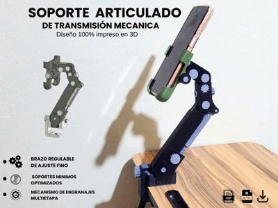
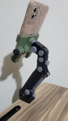
Articulated Cell Phone Holder


Print Profile(2)
Description
Boost Me (for free)
"If you liked this mechanical headache I designed, a Boost helps me pay for filament (and coffee) to keep creating homemade engineering pieces. Thanks for supporting the work!
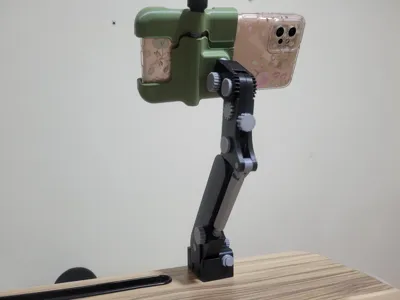
I designed this stand seeking the greatest possible comfort when adjusting the phone's position. The main idea is to use "controllers" in the form of worm screws to achieve a fine adjustment, something simple stands do not achieve
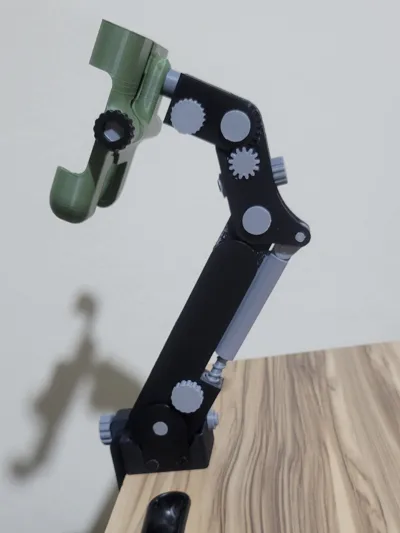
All movement is based on 90-degree transmissions that allow locking the position on each axis
How does the mechanism work?
I have divided the stand into three independent mechanical sections:
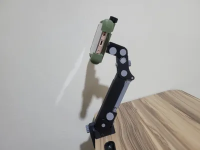
At the base: A worm screw moves a helical shaft which, in turn, drives a planetary gear. The ring gear is fixed to the first arm, allowing the inclination of the entire structure to be adjusted with strength and stability
On the first arm: I incorporated a similar mechanism, but here the helical shaft becomes a threaded rod. This acts as an actuator that pushes the second arm vertically, allowing control of height and reach
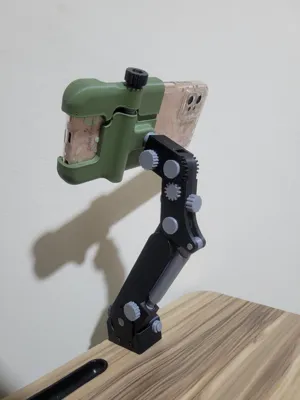
On the second arm: A 90° worm and helical shaft system moves two synchronized pinions. These create a lever movement to adjust the final angle of the phone, so it points exactly where you need it
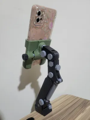
For rotation: I included a worm mechanism connected directly to the base of the clamp. This allows the phone to rotate between vertical and horizontal positions with precision, preventing the phone's weight from accidentally rotating it
Clamping (Jaw): I designed a manual screw-adjustable clamp. It is a direct pressure system that secures large phones (tested with over 100 mm width)
It's a homemade engineering project for those who enjoy visible mechanisms. It REQUIRES MINIMAL SUPPORTS ONLY ON SOME PARTS, it is OPTIMIZED TO THE MAXIMUM for easy printing and for each piece to fit into place. If you are looking for a stand that is not "more of the same", this is the one
Assembly Note (Important)
For the clamping jaw, the screw head has a hexagonal recess. By design, you must first assemble the screw in place and, once positioned, glue the head with a drop of adhesive (superglue). This ensures the mechanism is firm
Adjustment and Tolerances
The mechanism has been designed with a standard tolerance of 0.2mm to 0.25mm
If parts fit too tightly: Remember that each printer and filament is different. A bit of sanding on the joints or checking your flow rate calibration usually solves any fitting problem
ASSEMBLY VIDEO LINK
https://youtu.be/Q3e5ij2N6CI?si=7wMdzOaNwYrs2yaI
License
You shall not share, sub-license, sell, rent, host, transfer, or distribute in any way the digital or 3D printed versions of this object, nor any other derivative work of this object in its digital or physical format (including - but not limited to - remixes of this object, and hosting on other digital platforms). The objects may not be used without permission in any way whatsoever in which you charge money, or collect fees.
Comment & Rating (31)