
Exhaust Manifold Fabrication Kit - Multiple sizes!
Print Profile(3)

Description
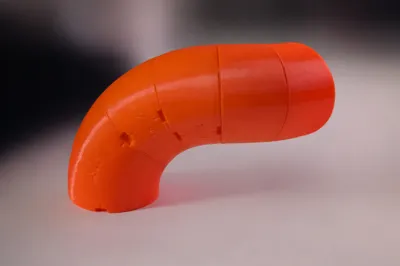
Exhaust Manifold Fabrication Kit V2
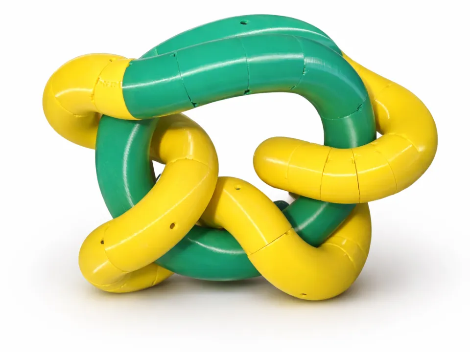
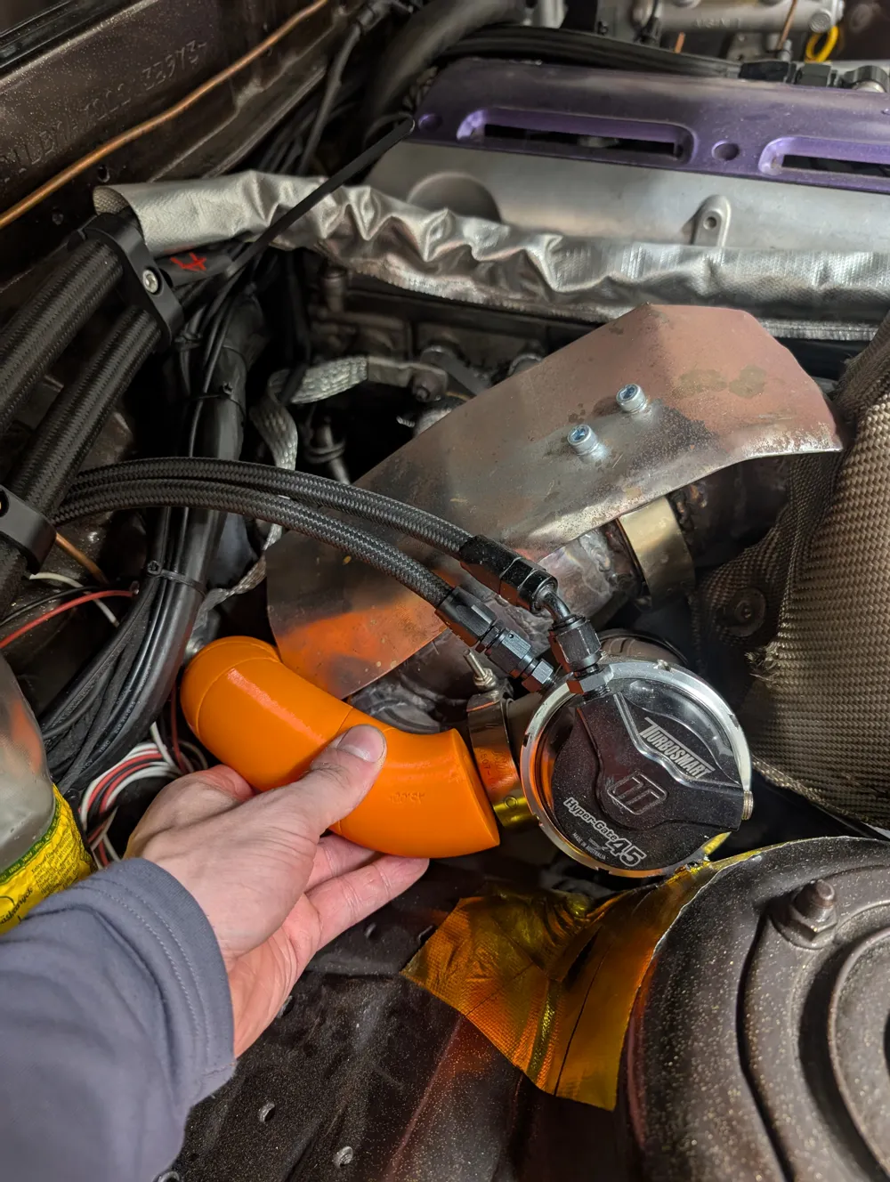
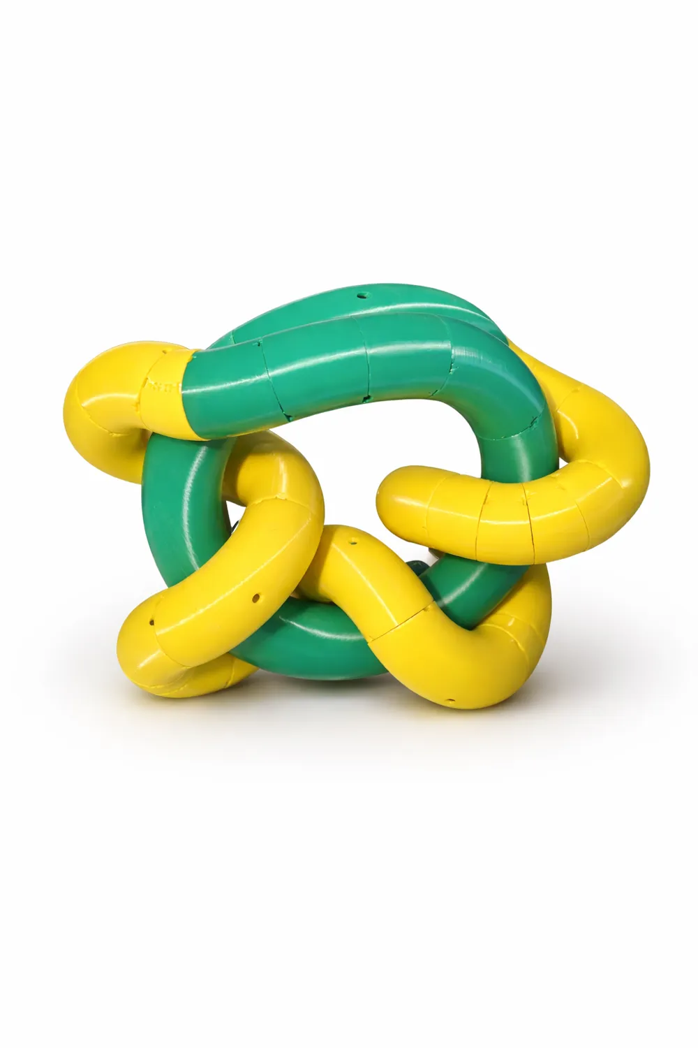
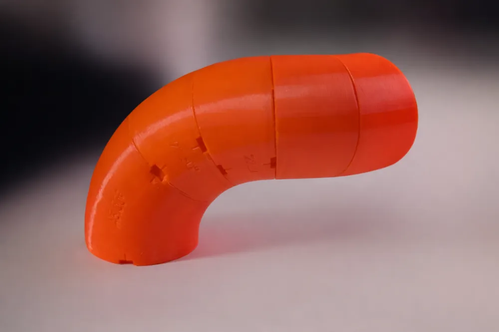
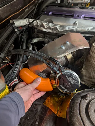
This kit is designed to simplify exhaust manifold design and mock-up during fabrication. With modular pipe sections and adjustable locking, you can quickly build and fine-tune complex routing directly in the engine bay before committing to final metal fabrication.
Available Sizes
All sizes include matching straight sections and bend sections.
| Kit Size | Straight Sections | Bend Angles | Centerline Radius (CLR) |
|---|---|---|---|
| 48.3 mm | 20–90 mm range | 22.5°, 45°, 90° | 57 mm, 108 mm |
| 2" | 20–90 mm range | 22.5°, 45°, 90° | 2", 3", 4" |
| 1.4" | 20–90 mm range | 22.5°, 45°, 90° | 1.5" |
| 1.5" | 20–90 mm range | 22.5°, 45°, 90° | 2.25", 2.5" |
| 1 3/4" | 20–90 mm range | 22.5°, 45°, 90° | 48 mm |

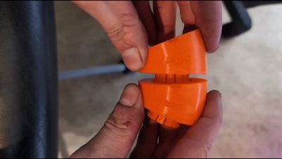
All parts feature an integrated snap-lock mechanism that holds the sections in place while still allowing precise adjustment. For best performance, the parts are intended to be 3D printed in PETG, providing the right balance of flexibility and durability for repeated assembly and adjustment.
V2 Update
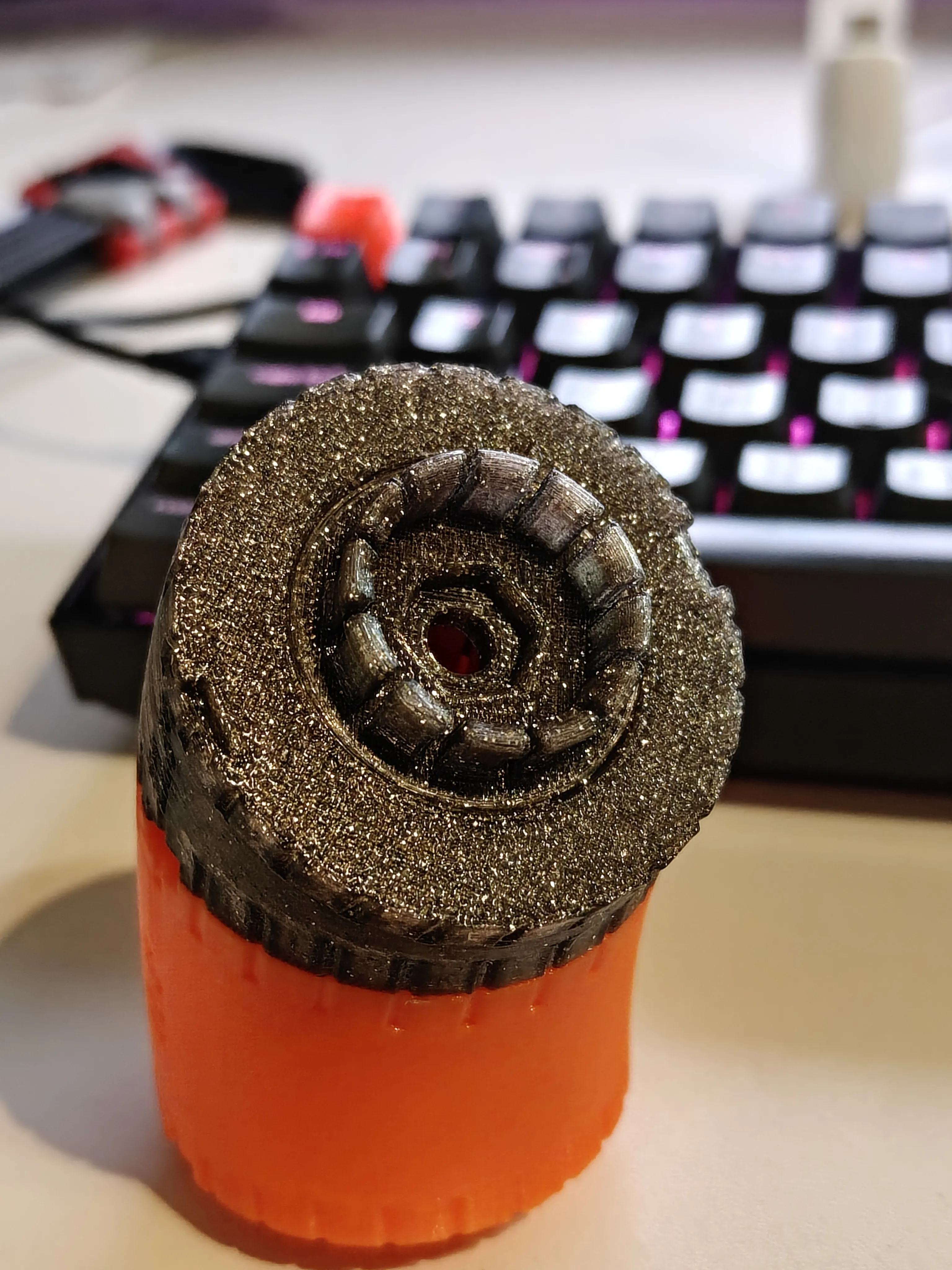
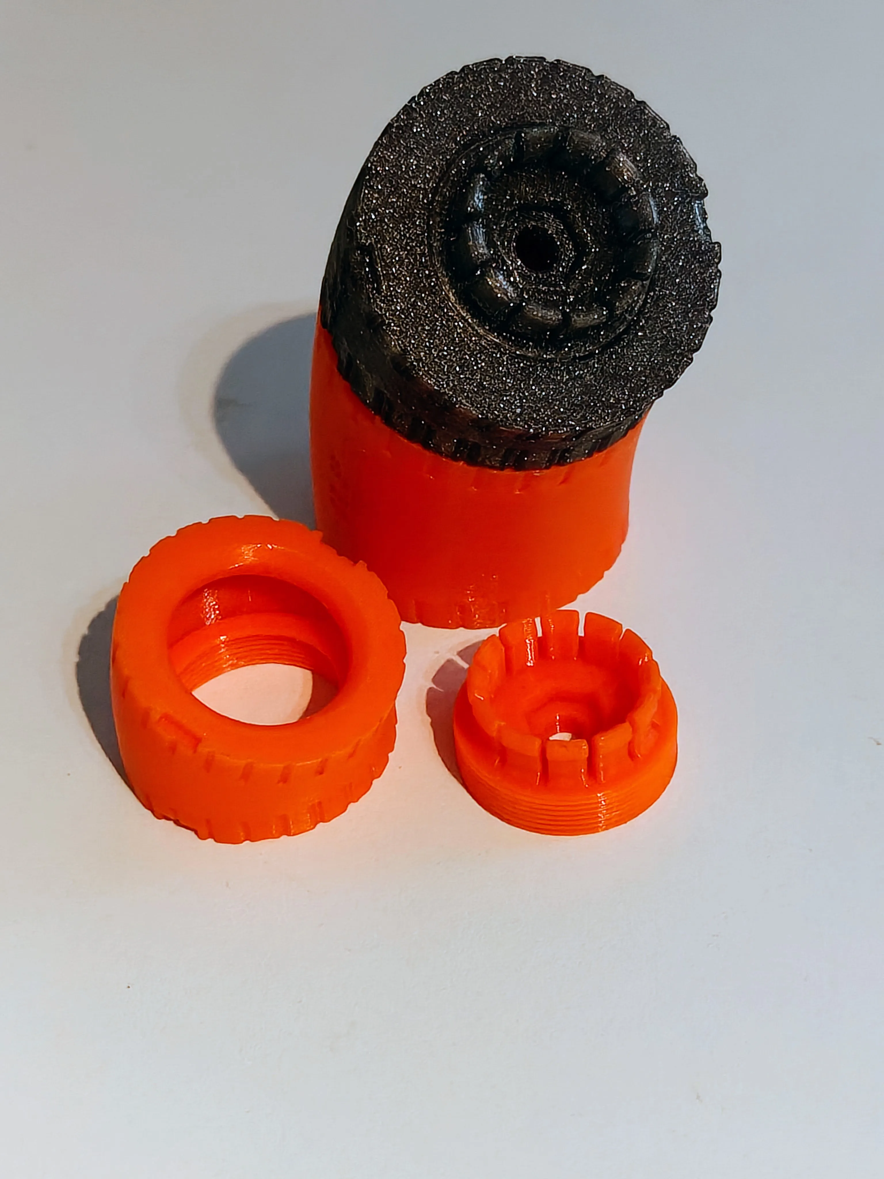
Version 2 introduces a redesigned locking system.
The locking mechanism is now a separate printed component instead of being integrated into the pipe sections.
Advantages:
- Reduced print time
- Easy replacement if the locking part becomes worn or damaged
- No support material required on the underside where the mount existed in the previous version
- Cleaner and more reliable prints
Kit Contents
- Pipe sections in 22.5°, 45°, and 90°
- Matching straight pipe sections
- Separate V2 locking plates
- Universal mounting flange
- Hardware provisions for M5 socket head screws
- Support for press-fit or glued-in M5 nuts (8 mm outer diameter)
Specifications
- Pipe outer diameters: 48.3 mm and supported imperial sizes
- Centerline radius options as listed above
- Material recommendation: PETG
- Integrated snap-lock system for positioning and adjustment
- Break-away tabs for easy separation of parts
Locking & Adjustment
- Adjustable using M5 socket head screws
- Locking plates allow rigid fixation once the desired angle is set
- Designed for repeated assembly and fine-tuning without wear
Assembly Notes
The threads on the locking mechanism may feel tight during initial assembly. This is intentional and part of the design to ensure a secure adjustment.
Before assembly:
- Ensure any remaining edges from supports are removed.
Installation:
- Use a 10 mm hex key
- Carefully work the mechanism back and forth during first installation
- Apply gradual force rather than forcing the threads
After initial break-in, threads becomes smoother while maintaining locking strength. You may add some glue to lock them together if the friction isn’t sufficient.
Notes & Future Versions
Additional diameters, bend radii, or configurations may be added in the future or provided upon request.
Ideal for turbo, naturally aspirated, and custom exhaust manifold builds where accurate fitment and efficient workflow matter. Save time, reduce guesswork, and achieve better results before moving on to welding and final fabrication.
Changelog
2026-03-16
- Introduced the V2 model and multiple sizes. Uploaded as a new profile – still compatible with the original design.
- Added 24 alignment reference lines around pipe sections for easier positioning
- Improved export workflow for all files
2026-03-09
License

You shall not share, sub-license, sell, rent, host, transfer, or distribute in any way the digital or 3D printed versions of this object, nor any other derivative work of this object in its digital or physical format (including - but not limited to - remixes of this object, and hosting on other digital platforms). The objects may not be used without permission in any way whatsoever in which you charge money, or collect fees.


Comment & Rating (59)