
CATAN card holder box
Print Profile(8)

Bill of Materials

Description
This is designed for cards for 67×43mm cards and 80×54mm
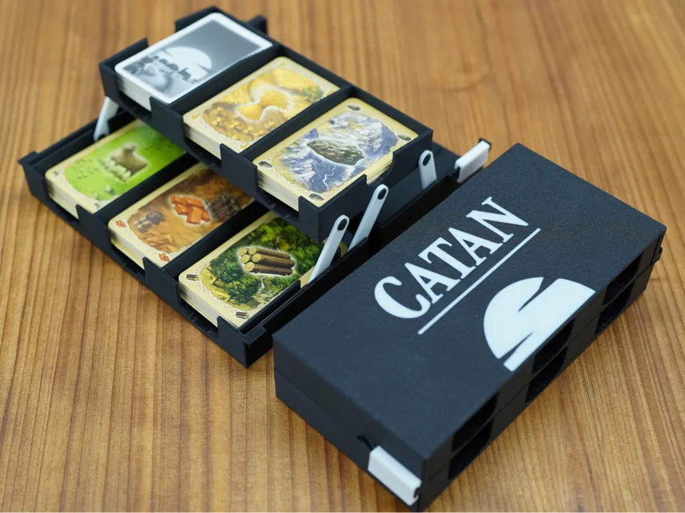
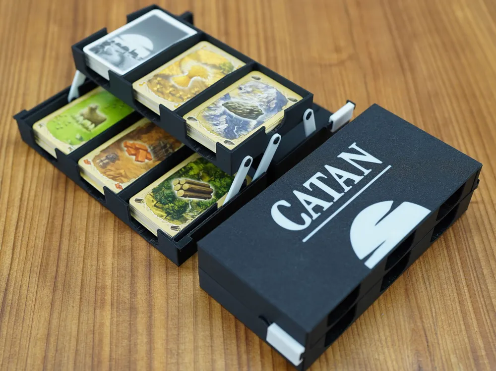
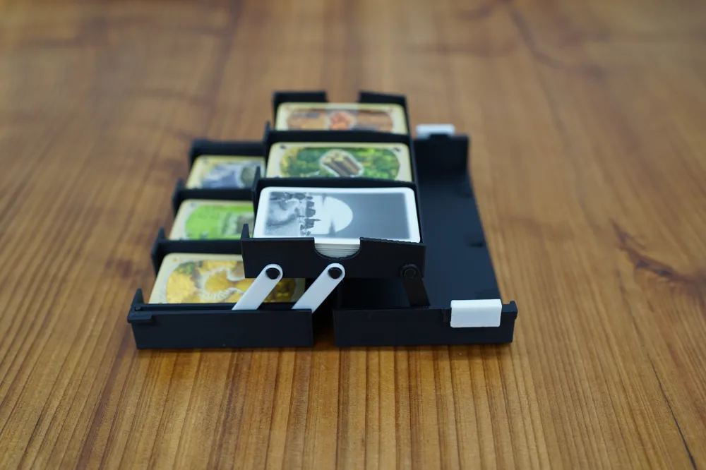
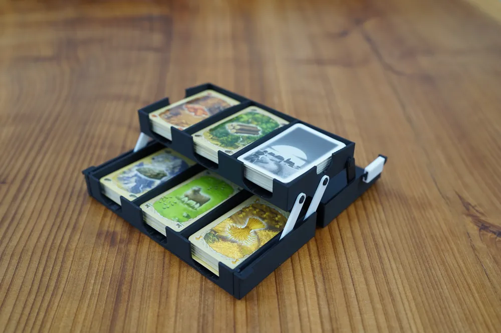
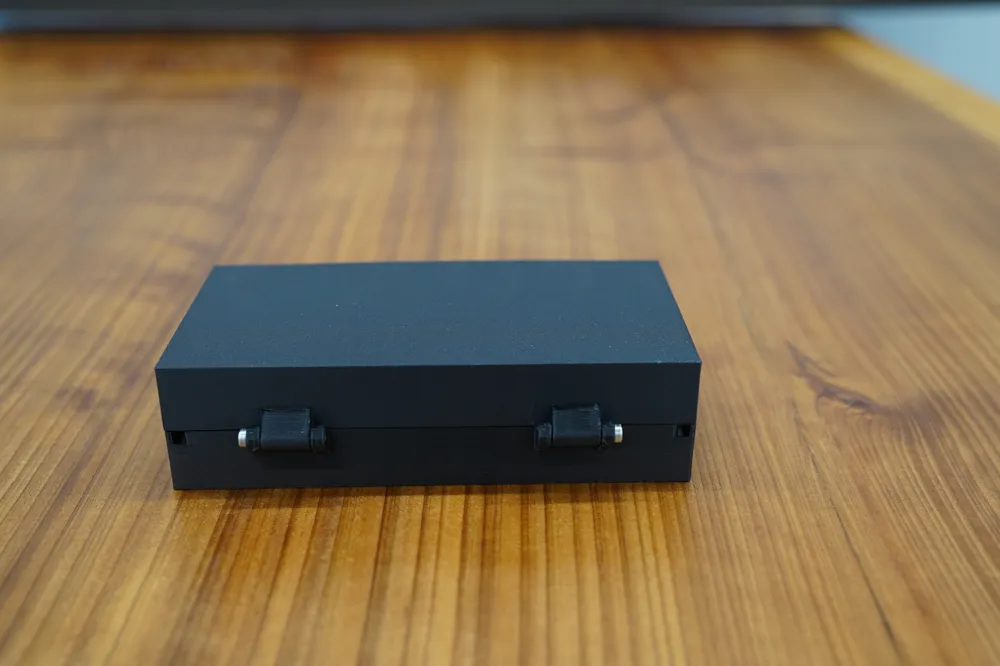
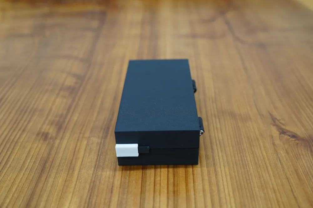
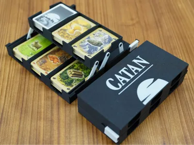
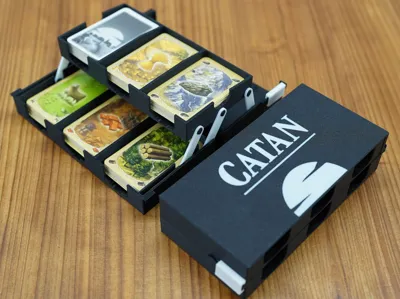
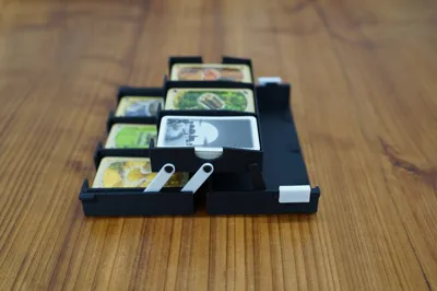
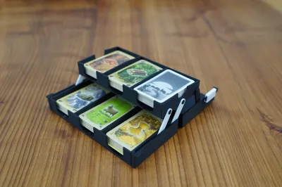
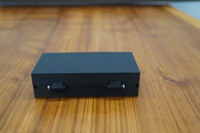
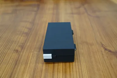
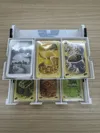
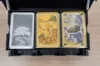
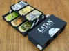
Six angled holders for resource and development card decks. It makes the decks easy to see during gameplay and store after play.
Before printing, please check the size of your cards and choose the appropriate model.
Boost Me (for free)
=========================【V4】=========================
version 4, the changes are as follows:
- Added support for sleeved cards (tested with sleeves sized 68×45 mm).
- Added guides to the Rod attachment points on the bottom.
This should make the rods less likely to come off and allow smoother opening and closing. - Added a protrusion to the hinge to reduce unintentional opening and closing, which makes the hinge slightly stiffer.
Printing model quick guide — for reference only.
No sleeved card | With sleeved card | |
| CATAN Standard box | 【V4_A】67×43mm | 【V4_A】67×43mm |
| Catan Standard box with Expansion pack | 【V4_A】67×43mm | 【V4_B】67×43mm |
Parts Description
3 Large Structural Parts
- Bottom
- Top Outer Panel (has protrusions on the inner side walls)
- Top Inner Panel (has three protrusions on the side walls)
8 Additional Large Parts
- Rods ×6 (used to connect the large parts. The holes on the two ends of each rod are slightly different — one side has a step/ridge, the other does not.)
- Lid hinge parts ×2 (parts for the opening/closing mechanism)
Assembly Instructions
0. Print all parts.
1. Attach rods to the front two protrusions of the Top Inner Panel (4 connection points total).
At this time, use the hole with the step on the rod, and attach it so that the step remains visible. Hooking it in place helps with attachment.
2. Attach the other end of the rods from Step 1 to the protrusions on the Bottom (4 connection points total).
3. Attach the lid hinge parts to the Top Outer Panel. This step may require a bit of force.
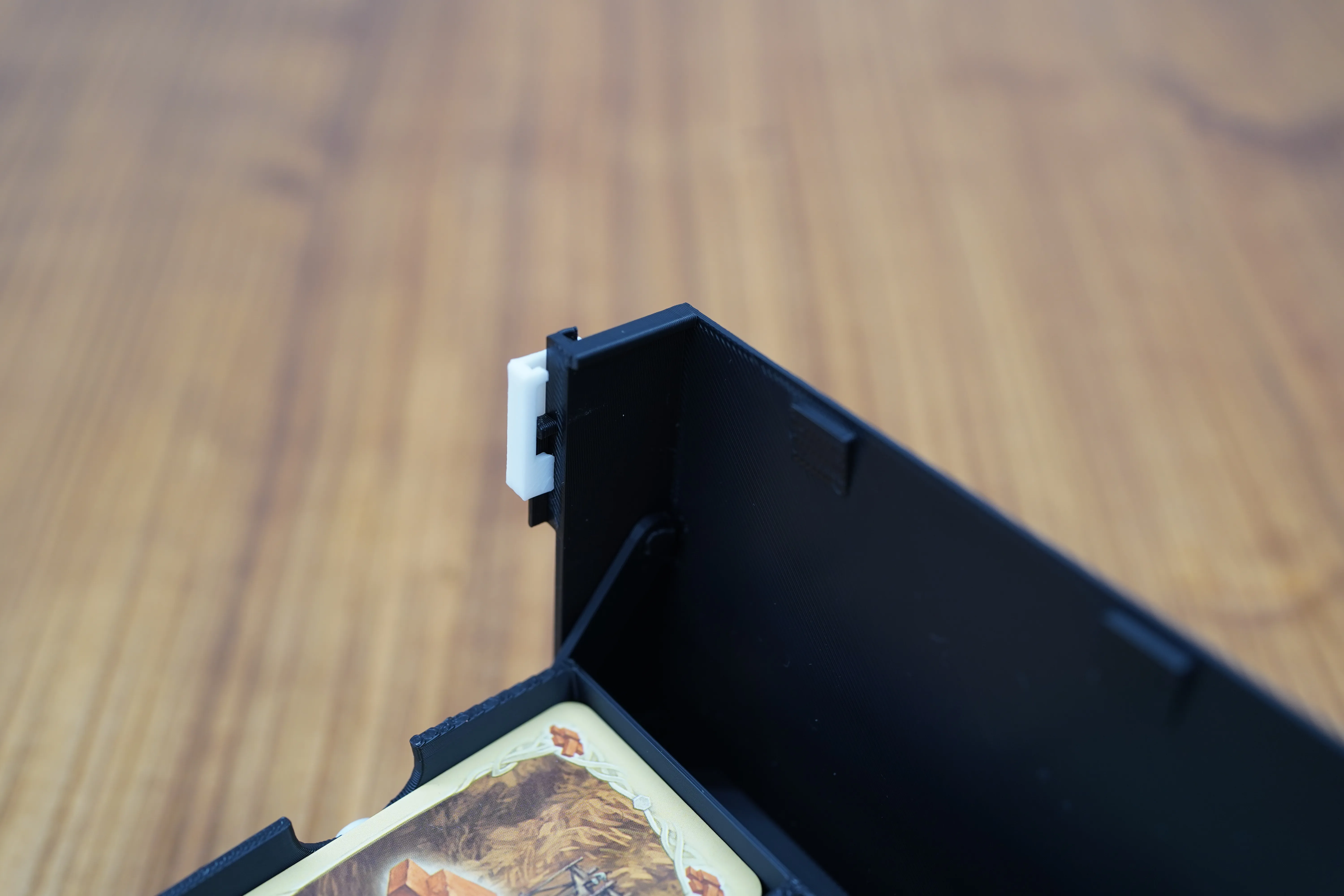
4. Attach rods to the protrusions on the Top Outer Panel from Step 3.
This time, use the side of the rod without the step, and attach it so the stepped side faces outward and remains visible.
5. Connect the protrusions from Step 4 to the remaining protrusions on the Top Inner Panel.
6. Attach the outer screws.
M3 × 20 screws seem to fit well.
======================================================
=========================【V3】=========================
version 3, the changes are as follows:
- The outer corners have been slightly rounded (improves the feel of the edges).
- Updated the "CATAN" text design.
==========================================================================
====================【V2】====================
version 2, the changes are as follows:
- The Bottom Outer Panel and Bottom Inner Panel have been integrated into a single panel.
- The “CATAN” text has been added to the Top Outer Panel.
==========================================
====================【V1】====================
Parts Description
4 Large Structural Parts
- Bottom Outer Panel (has two indentations on the inner side walls)
- Bottom Inner Panel (has two protrusions on the side walls)
- Top Outer Panel (has protrusions on the inner side walls)
- Top Inner Panel (has three protrusions on the side walls)
8 Additional Large Parts
- Rods ×6 (used to connect the large parts. The holes on the two ends of each rod are slightly different — one side has a step/ridge, the other does not.)
- Lid hinge parts ×2 (parts for the opening/closing mechanism)
Assembly Instructions
0. Print all parts.
1. Attach rods to the front two protrusions of the Top Inner Panel (4 connection points total).
At this time, use the hole with the step on the rod, and attach it so that the step remains visible. Hooking it in place helps with attachment.
2. Attach the other end of the rods from Step 1 to the protrusions on the Bottom Inner Panel (4 connection points total).
3. Attach the Bottom Outer Panel to the Bottom Inner Panel from Step 2.
Be careful, as the rods may come loose easily at this stage.
4. Attach the lid hinge parts to the Top Outer Panel.This step may require a bit of force.
5. Attach rods to the protrusions on the Top Outer Panel from Step 4.
This time, use the side of the rod without the step, and attach it so the stepped side faces outward and remains visible.
6. Connect the protrusions from Step 5 to the remaining protrusions on the Top Inner Panel.
7. Attach the outer screws.
M3 × 20 screws seem to fit well.
========================================
License

You shall not share, sub-license, sell, rent, host, transfer, or distribute in any way the digital or 3D printed versions of this object, nor any other derivative work of this object in its digital or physical format (including - but not limited to - remixes of this object, and hosting on other digital platforms). The objects may not be used without permission in any way whatsoever in which you charge money, or collect fees.


Comment & Rating (150)