Mara Jade Lightsaber


Print Profile(2)

Description
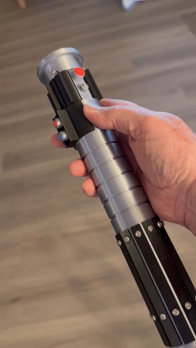
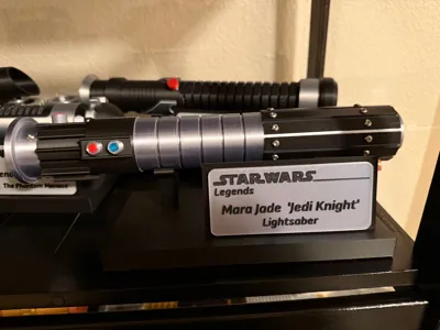
After viewing several variations online, this is my version of Mara Jade’s light saber. I used several items not 3d printed. I do not like gluing everything together, so I used screws this time. While I used chrome M3 screws I purchased from Amazon, I did provide these as optional prints as M3x6 button head screws and M6x12 socket head screws. You will need thirty and three respectively. I will caution whether you use real chrome screws or print your own, they are very easy to strip in the PLA plastic. I also used a 3.5-inch flashlight in the hilt to light up the extended blade. I used the Hortsun flashlight from Amazon - https://www.amazon.com/dp/B0C9H7CPZM?ref=ppx_yo2ov_dt_b_fed_asin_title&th=1. Similar flashlights are available but may have slots positioned in slightly different positions.
The filament used includes silver silk, black, red, red copper silk and translucent blue and silver PETG for support interface. I used PLA for the items and used the PETG for support interface.
I try to use threaded pieces for most of the assembly to reduce the requirement for gluing pieces, however some pieces will require glue.
I have several suggestions for printing successfully:
1) I suggest you use a PEI smooth plate instead of the textured plate. The textured PEI plate normally works but the tolerances may vary.
2) I strongly suggest, as I often do, make sure you use an appropriate support interface filament. I normally use PLA as my primary filament and use PETG for the interface.
3) For support type, I suggest using Tree and ‘Slim Tree’.
4) I have provided thirteen plates, but you can easily combine plates with similar filament requirements if you like. The thirteen plates provide several options.
With the above considered, let’s begin description of build plates. I do not try to limit number of plates. I do extra plates for ease of development
Printing configurations for Bambu Studio:
Plate 1:

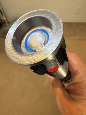
Plate includes the Emitter Cowl, Emitter and Tab, the Switch Shield and two screw covers. The Emitter and Tab are printed together. Originally, all these were printed in Silver Silk, but viewing a few versions on-line colored the shield black. I eventually printed this in black.
Plate 2:
Plate 2 contains the Mid Hilt section and requires the most support. It has support on the outside, seen here, and inside bottom for the threads. Support Type used was ‘Tree (auto)’ and Style ‘Tree Slim”. When removing the support from the threaded areas, make sure you remove the support interface which occasionally requires more effort. The Mid Hilt could easily be moved to Plate 1.


Plate 3:
Contains a single element: the Aft Hilt Section in Silver Silk. The Aft Hilt has 24 screw holes and a hole for the Belt Clip Knob but only requires support for the threads in the bottom.
Plate 4:

This plate only has one item, the Front Red and Silver Button, also called the ‘trigger’ button. I recommend printing this in the orientation shown, with the stem down, as opposed to the Bambu Studio recommendation with the red button down. While the stem down orientation requires support, with PETG as support interface, it is very easy to remove, and it makes the Red Dome much smoother.

Plate 5:
Plate 5 contains 24 Aft Hilt Slats: I printed these in black, but most of the images online have these silver. When I saw the images with the slats (and the shield) in black, I really liked the contrast. Note that 22 of the slats are identical but slats 7 and 8 have a cutout for the belt clip knob.
Plate 6:
This plate contains the locking rod and light holder. These are on a separate plate because, since they are not seen, they can be printed in any filament. Note that the Light Holder is in two pieces that break apart after printing but is easier to print together.

Plates 7 and 8:
Another instance of almost empty plates. These are the red and blue (transparent) buttons that go into the screw covers (from Plate 1) on the second section of the hilt. I print these at 100% infill.
 P
P
Plate 9:
First optional plate – This plate contains the two sizes of the screw head covers for Plate 1. The first was printed with a 0.05mm offset between the M3 socket head screw and the cover, same as Plate 1. If the 0.05mm offset makes it too hard to insert the socket head M3 screw, then the 0.1 will make it easier. If the 0.1mm version is still too hard, then I suggest experimenting with the slicer to enlarge the hole or slightly heating the cover and inserting the screw head.

Plate 10:
Plate 10 contains the five-element blade. I printed this in Translucent blue. This is a single STL for all five blades. If you need to print a single section, maybe if one breaks, then you will need to split this in your slicer.

Plate 11:
Plate 11 is another sparse plate. It contains the Belt Clip Knob. I printed this in Red Copper, but gold would also look good. This requires support for the second level but is easily removed using PETG interface.

Plate 12:
This is an optional plate for a belt clip. Several people in the past have asked for a belt clip to carry their saber. This answers those requests. There are two versions: one that slips over a belt and one that has the belt slide through the clip.

Plate 13:
This plate is for anyone who doesn’t have access to metal M3 screws or those who like to have as much 3-D printed as possible. This has a single M3x6 button head screw and you will need thirty. The second is a M3x12 socket head screw and you will need three. In both cases, please be careful when screwing these into the model – it is easy the strip the threads in plastic.
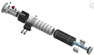
Well, that covers all the individual plates. Now, let’s go through the assembly.
Assembly:
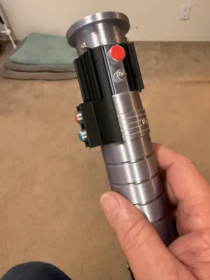
First, I will assume you have the screws available. From Plate 1, insert the Emitter and tab into the Emitter Cowl. This should be a tight fit. Make sure you align the top switch plate with the slot in the cowl. Then carefully screw in the three screws to secure the two pieces.

Next, insert the locking rod into the Emitter. The locking rod has two bumps on it to help keep it in the locked position. If this is too tight, then you can lightly sand the tops, but don’t sand too much and defeat the purpose. It should slightly ‘snap’ into the two positions, forward and aft. You can use a pointed tool to move the locking rod between the two positions. When you have exercised the locking rod enough to make it acceptable then you can use the ‘trigger’ button, without gluing yet, to move the rod back and forth to loosen it again. You will notice that the hole for the Red and Silver trigger Button is also not just oval. This also helps with the ‘snapping’ action. If adding the trigger button makes it too hard to move, then you can sand off a little of the edges of the trigger button hole.


Important step: When you are ready to do the final install of the trigger button, you will need glue. Be very careful to only add a very small amount onto the stem end. You do not want the glue to squeeze out and get on the emitter surface. After adding the glue and inserting the trigger button, hold in place for about five seconds, after five seconds keep moving the trigger button forward and back for about thirty seconds to make sure you do not glue the locking rod to the emitter. You can add the m3x6 screw at any time.
Now, install the split black section onto the emitter. This should be slightly tight but is easily opened to fit. You will secure this with the Mid Hilt section.


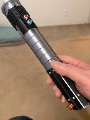
The Mid Hilt section includes the Mid Hilt and a switch plate and shield. You can install the switch plate either before you screw this section into the emitter or afterwards. As mentioned earlier, the switch plate can be either silver or black.
The switch plate is secured to the Mid Hilt by two M3x12 socket head screws. Before securing the switch plate, insert the M3x12 socket head screws into the covers. Then install the red and blue ‘lens’.

The inside surface of the switch plate has two levels Be sure to correctly orient the switch plate onto the Mid Hilt. Secure the switch plate to the Mid Hilt with the M3x12 covered screws, finger tight.

Screw the Mid Hilt section into the emitter and screw in the three M3x6 socket head screws around the Mid Hilt. You can add the blade to this assembly or wait until we finish the Aft Hilt.


So, next, we work on the Aft Hilt. The Aft Hilt has twelve slats around it, attached by twenty-four M3x6 button head screws. The twenty-four slats are all identical except for slats 7 and 8. They have a cutout for the clip knob at the bottom. The clip knob is secured with a socket head M3x12 screw.

Next, we install the 3.5-inch mini flashlight. The flashlight is held in place with a flashlight ‘holder.’ The holder is in two pieces and wrap around the button end of the flashlight. The outside case of the flashlight has grooves that coincide with the inside of the holder. Once the holder is positioned around the flashlight, insert this assembly into the Aft Hilt and secure with the end cap.

All that is left to do is insert the blade and screw the Aft Hilt into the Mid Hilt section, admire your work and turn on the flashlight by pushing the end button.

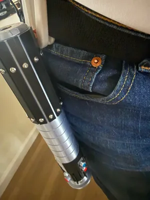
When finished, you then can use the belt clip to attach it to your side.
I hope this brings a lot of enjoyment and please post a picture of your success.

License
You shall not share, sub-license, sell, rent, host, transfer, or distribute in any way the digital or 3D printed versions of this object, nor any other derivative work of this object in its digital or physical format (including - but not limited to - remixes of this object, and hosting on other digital platforms). The objects may not be used without permission in any way whatsoever in which you charge money, or collect fees.
Comment & Rating (5)