IronWave Switch Plates - 16x76mm Corrugated Metal


Print Profile(3)

Description
These models are part of the Corrugated Iron Collection there's a closely related backing plate here - Clipsal Corrugated Metal Plate - also for switches and outlets, 1 and 2 gang.
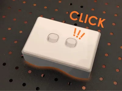
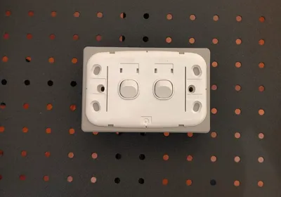
The 120x80 mm switch mounting blocks are designed to attach a light switch, power socket or control panel to corrugated metal sheet of 16 mm x 76 mm profile. Although you can change this profile by scaling (see below).
There are several designs:
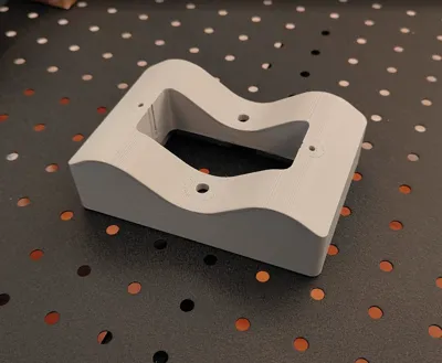
- Low profile - Includes recessed pockets at the switch/sockets screw‑mounting points. Some low‑profile switch mounts extend below the mounting surface, and if a standard switch is used on this block, over‑tightening the screws can cause them to pull through the back of the switch because there’s no solid backing behind those points. If you plan to use this model, consider measuring this gap and rescaling the included small standoffs to provide proper backing support. OR Add some more reinforcing modifiers at the screw down points on the perimeter of the switch and use those. This is about how the switch hardware attaches to the mounting block not the block to the wall.
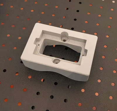
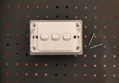
- Standard - Is designed for a switch that mounts to a flat surface (this is more likely the one you want). There is a flat solid surface at the switch screw points.
- Rectangular Mounting Block - Simpler design similar to Standard above, but with a smaller pass-through, and more face-plate space for mounting. When you do, don't forget to add reinforcing at those points (see below).
- Alternative (not here) - IronWave Spark - For the Clipsal Iconic outdoor series
Key switch plate fixing dimensions
- Width: 120 mm Height: 80 mm
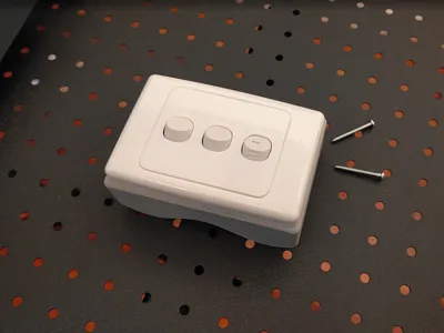
- Switch mount screw-to-screw spacing - 84 mm (centre-to-centre) complies with AS/NZS 3112 (socket requirements). Designed to accept the standard 3.5 mm mounting screw with fine pitch. 32 or 50 mm length. Pilot hole is 3 mm diameter.
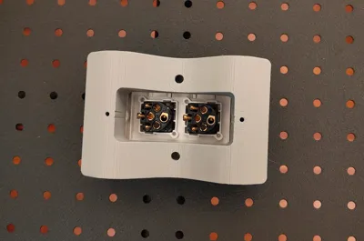
- Mounting box height (internal) - 70 mm
- Mounting box width (internal) - 84 mm internal
- Mounting box depth (internal minimum clearance to sheeting) - 23 mm
Design Considerations
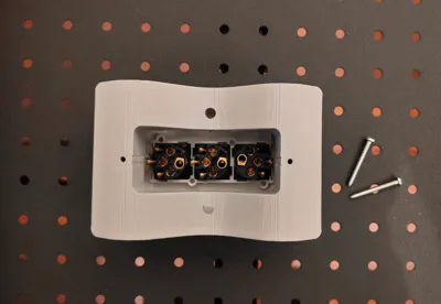
Wall Mounting Screws - All models were designed to accept a 15 mm head and 6 mm shaft of this style. Of course, you can use whatever screw you have that fits and is also fit for purpose.

Corrugation‑matching - The base plate is designed for a penetration close to the corrugation peak. As for orientation of switches in particular, these mounting blocks will suit both landscape and portrait fitments by reorienting the switches 90 degrees in the face plate. For sockets this won't work. If you require a custom corrugation phase or offset, feel free to request it.
Fixing considerations - Fixing screw locations positioned on the corrugation peaks into purlins or framing and sized for standard roofing screws: Head clearance: 15 mm / Shaft diameter: 6 mm. Shaft diameter is deliberately tight to help weather sealing. Roofing screws normally fasten through the crest of a sheet into wall framing or purlins. This maximizes strength and avoids placing penetrations in valleys where water collects. Depending on the orientation of the corrugations one of the 2 screw models will align with the screw-line and allow you to get both screws into a solid backing. In the case of a switch, a pair of pre-drilled 4mm pilot holes (don't drive the screws un-piloted) and carefully driven roofing screws into the sheet where there is no backing will secure the mount for most light-duty attachments (switches and control panels). Sockets may be marginal as they typically require a firmer substrate to resist plug‑in/plug‑out forces. NOTE: You can also use pop-rivets, although the existing mounting points are not designed for these (ask).
Weatherproofing - For outdoor positioning, put a generous bead of silicone or polyurethane sealant around the entire back of the plate and some in the mounting screw sockets before screwing down. The model clearances assume the screw weather-seal washer will be removed and using sealant instead if the screw has washers. You may also consider epoxy or polyurethane construction adhesives where maximum strength is needed and framing can't be used to anchor the plate. Also check the adhesive chemistry matches your filament type - you don't want to dissolve it!
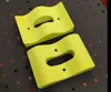
What are the yellow cylinders? - Don't worry, the yellow cylinders are not printed! They are modifiers, shapes that change how the model is printed where they intersect with it (see below). Here they are set to generate 100% solid infill to strengthen mounting points where screws are used. Yes you could print the entire plate with 100% infill but this would be an unnecessary waste of filament and increase print time from 2-3x !
Adding more reinforcers for additional switch plate mounting screws.
You may want to screw the switch plate to the surrounding mounts as indicated here, to stop the plate wandering. In this case, you will want to reinforce these points.
1. Select the modifier - Modifiers are found under the Process header in the Objects section (see below), click the modifier you want to duplicate.
2. Duplicate the modifier - Use your system’s copy/paste shortcuts to create a second instance: Windows: Ctrl+C, Ctrl+V. macOS: Cmd+C, Cmd+V. You’ll now have a pair of modifiers stacked in the same location. The next step will reposition only the newly created one.
3. Position the reinforcer - On the model, click and drag the selected reinforcer to the exact spot where you plan to drill or drive a screw through the backing plate.4. A detail - I have positioned the modifiers .4 mm (2 layers) back from the front surface of the model, where its all still solid, so they don't cause a change in surface texture.

Corrugation Height Changes:
To measure the corrugation height, follow these steps:
Place a ruler flat across the corrugations.
Use a caliper's depth gauge to measure the distance to the base of the corrugation. Don't forget to subtract the thickness of the ruler.
Alternatively, you can use a second ruler to measure from the underside of the top ruler to the base.
The corrugation height for this model is 16 mm. To adjust the backplate for a different height, use the scaling formula below:
Scaling Formula:
( Desired Height ÷ 16 ) x 100 = Scaling Factor percent - Deselect ‘uniform scale’ to apply only to Z.
Example Calculation:
For a desired 17 mm height:
(17 mm ÷ 16 mm) x 100 = 106.25 - Z-axis scaling

Corrugation Width Changes (pitch):
The typical (Australian) peak-to-peak distance is 76 mm (3 inches). However, this can vary slightly depending on the manufacturer and the specific profile of the corrugated sheet. You can scale X/Y by the same amount to change this.
( Desired width / 76 ) x 100 = Scaling Factor percent - Deselect ‘uniform scale’ and apply only to X & Y.
Print considerations
Supports - The model prints upside-down so the presentation face is against the print bed. The print profile includes tree-supports for the mounting screw holes, as theres a 12 mm ledge and 15 mm screw holes step-down suspended in mid-air. After printing you will need to tear these out with a pair of pliers. Yes the interior looks a little rough, but this isn't going to be seen.
Material Choice for Printing - While PLA could work here - given metal conducts heat, if this is used outdoors, I would recommend PETG-HF, particularly if the area is in direct sunlight. PLA will be fine if the location is under shade (verandah or inside a shed for example).
Metal + Mains voltage electricity + Screws - what could possibly go wrong? Well a lot less if you use this backing plate :)
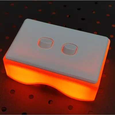
Get Creative
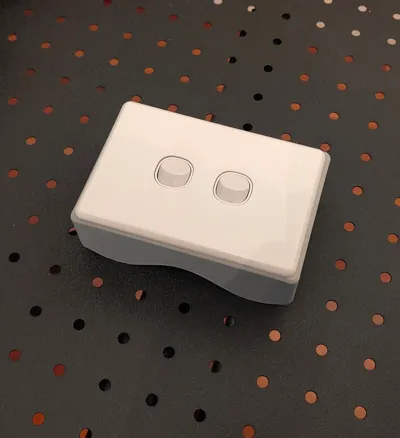
Why not print it in white and add some LEDs inside

Enjoy!
License
You may create derivative works based on this object, provided that all such derivative works are published exclusively on the MakerWorld platform and include proper attribution to the original creator. You may not share, upload, host, distribute, or publish this object—or any derivative work of this object—on any other digital platform, marketplace, or distribution channel. Commercial use of this object and any derivative works is strictly prohibited. This includes, but is not limited to, selling, renting, sublicensing, or using the object in any context in which you receive monetary compensation or other financial benefits.
Comment & Rating (4)