Search models, users, collections, and posts

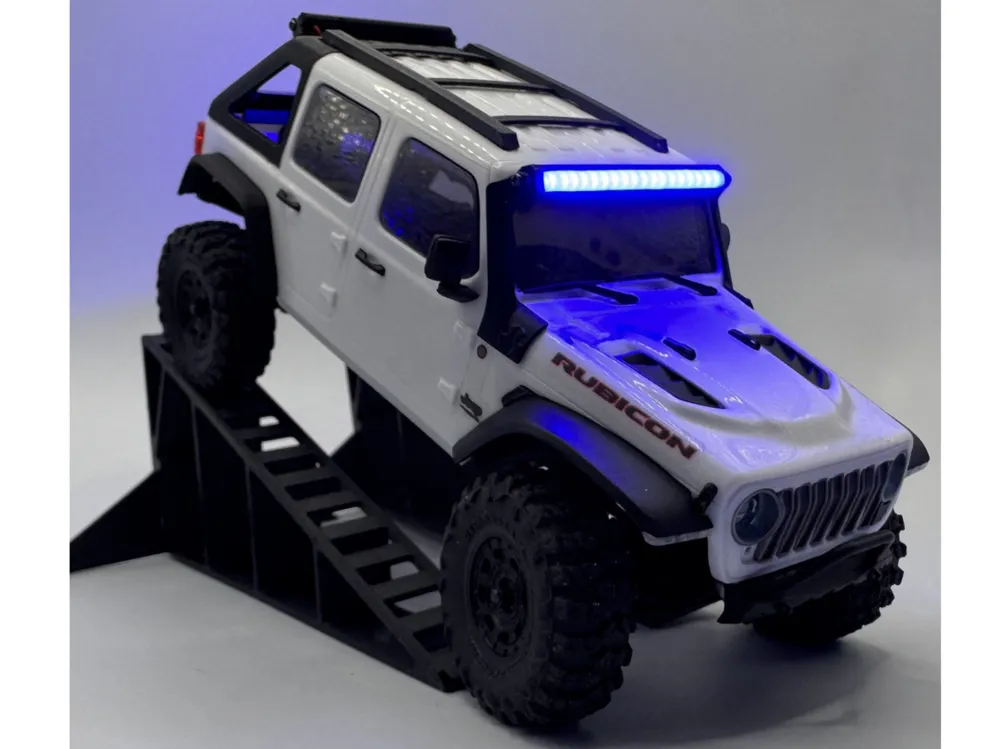
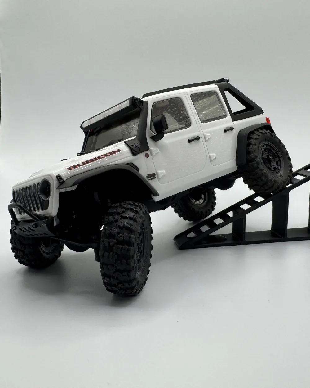
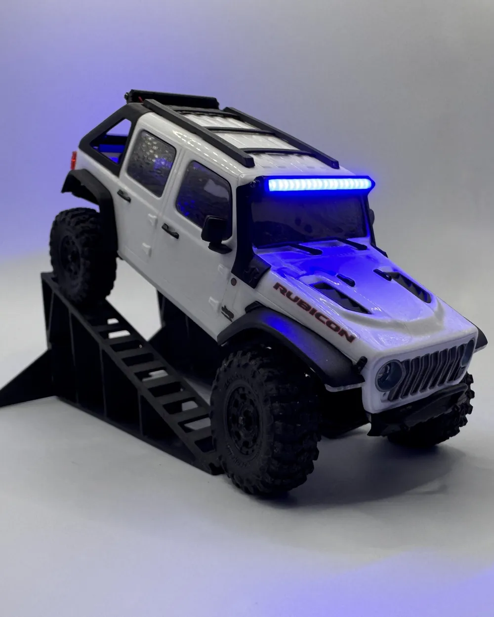
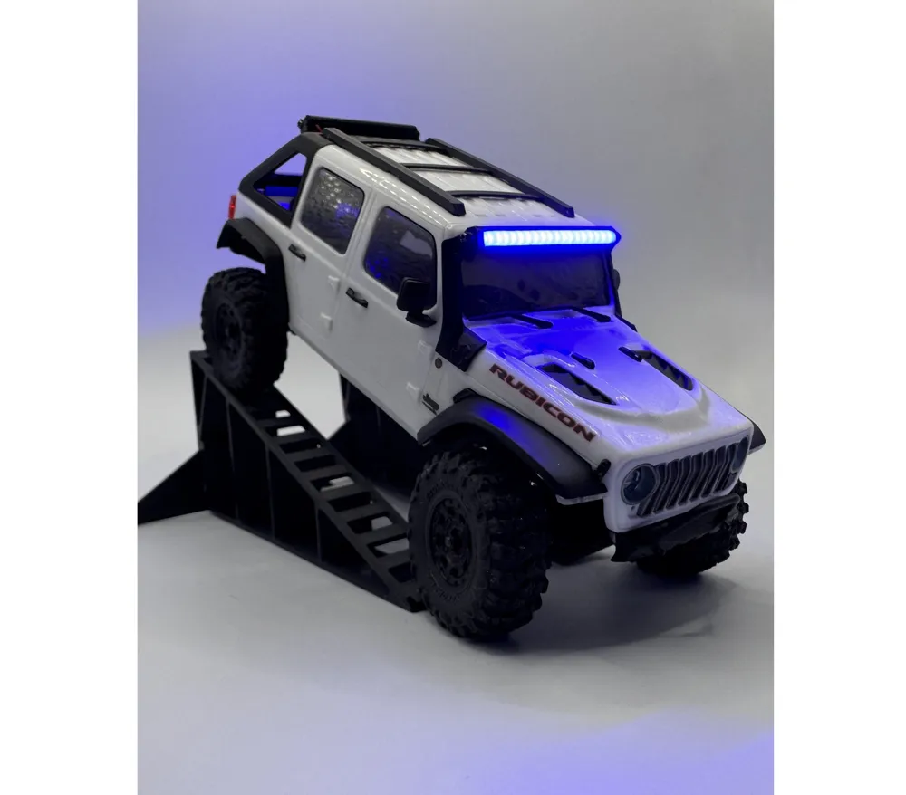
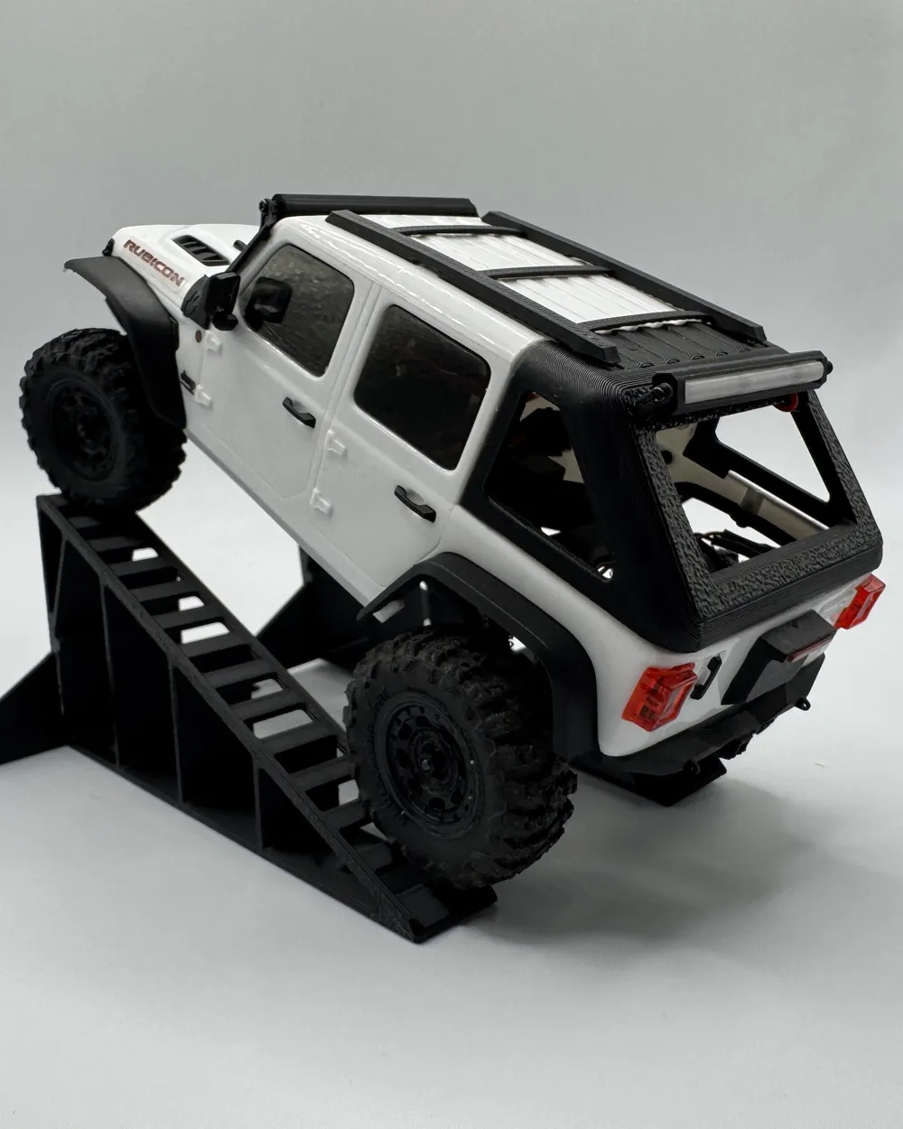
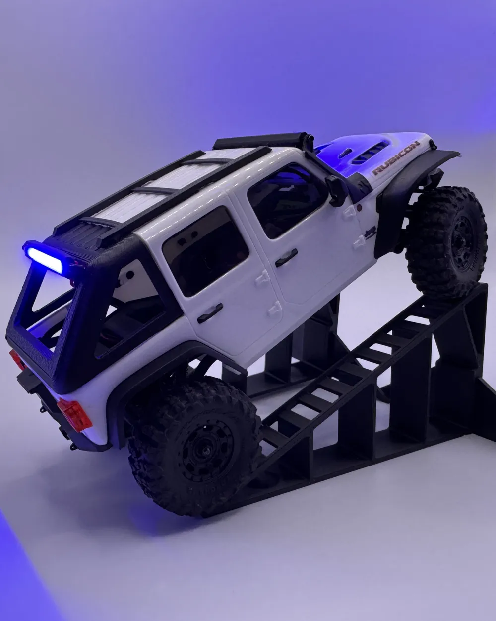
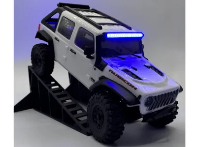
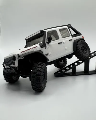
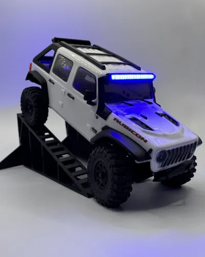
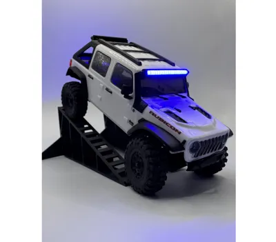
SCX30 - Jeep Gladiator Light Bars
IP Report
Print Profile(2)

SMALL PRINTBED VERSION - 0.16mm layer, 2 walls, 15% infill
Designer
51 min
2 plates

0.16mm layer, 3 walls, 15% infill
Designer
55 min
2 plates
Open in Bambu Studio
Boost
44
98
7
0
62
19
Released
Description
This model is a continuation in my efforts to create my optimal Jeep SCX30.
- The Front Light Bar is a drop-in replacement for the existing non-functional bulbs.
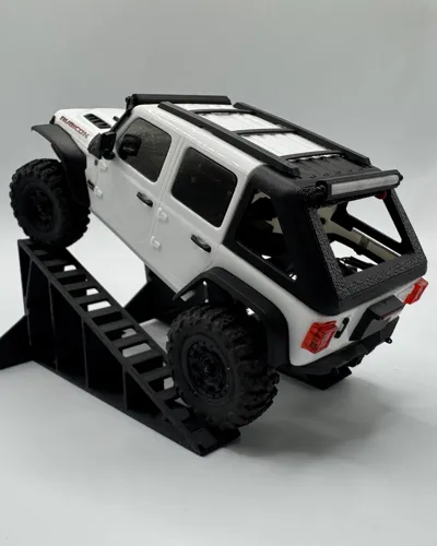
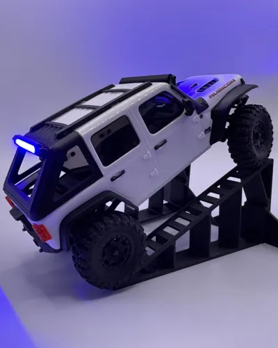
- The Rear Light Bar mounts to stands that screw into the Fastback body allowing for free rotation of the light. (See here for my FastBack model without lights)
WHAT YOU'LL NEED:
- 5V COB LED Strips - 2.7mm width (These COBs are popular in FPV racing)
- M1 x 3mm Screws
- PH 1.25 Male Connector (Optional, can be spliced into existing lights)
GUIDE:
- This Guide assumes the Fast-Back and Roof-Rack portion have already been installed onto the body. For guidance on doing that, refer to my original link above.
- Cut two strips of your COB lights. (Rear - 31mm | Front - 38mm) DO NOT SOLDER YET
- Remove original Front Light Bar
- Place the Front Light Bar into the cradle, and with a fine point, make a small mark on the windshield where the wire hole lines up.
- Remove The SCX30 Window Plastic section, then make a small hole in the marked location large enough for two small gauge wires. (I used Silicone 30AWG for my application.
- Feed two wires through the window hole created, then through the rear hole of the light bar.
- Solder the wire ends to the COB strip (38mm), then remove backing and press into place.
- Feed two more longer wires through the rear light bar, then solder to the COB strip (31mm) and press in place.
- Install the rear light rack posts onto the light bar with two M1 x 3mm screws.
- Line up the rear light rack with posts installed, then install to the Fast Back body with two M1 x 3mm screws.
- You should now have two sets of wires that feed inside the body for each light bar. It's up to you how you want to wire everything, but I'll leave how mine ended up below:
- Solder PH positive - Rear Positive,
- Rear Negative - Front Positive,
- Front Negative - Rear Brakes Positive,
- Rear Brakes Negative - PH Negative
TIPS:
- Always use heat shrink when soldering wire connections together.
- Use double-sided tape to tuck the wiring along the ceiling corner throughout the body, then down the pillar to keep wiring out of sight.
- A Micro-Switch can be added in series to the PH connector to allow the lights to be independently turned off when not required.
- Ensure your front window hole accounts for the angle you want to tilt the light bar. If the hole is too low, the light bar will be permanently tilted upwards.
License

This user content is licensed under a Standard Digital File License.
You shall not share, sub-license, sell, rent, host, transfer, or distribute in any way the digital or 3D printed versions of this object, nor any other derivative work of this object in its digital or physical format (including - but not limited to - remixes of this object, and hosting on other digital platforms). The objects may not be used without permission in any way whatsoever in which you charge money, or collect fees.


Comment & Rating (7)