
WLED Sync Beast - Esp32 Ethernet
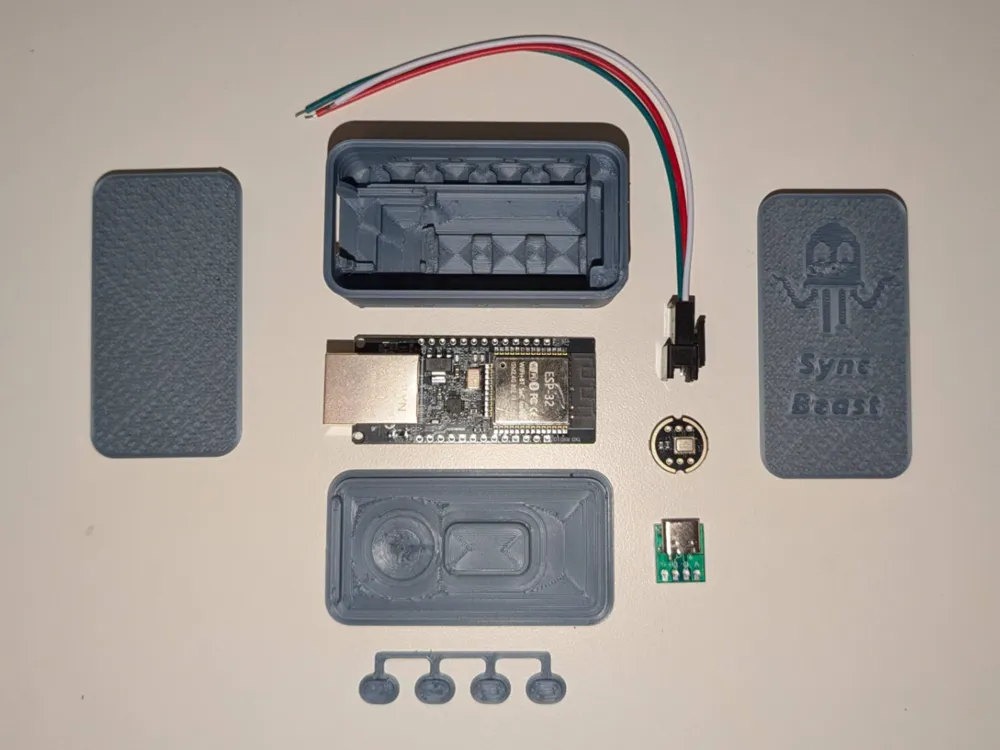
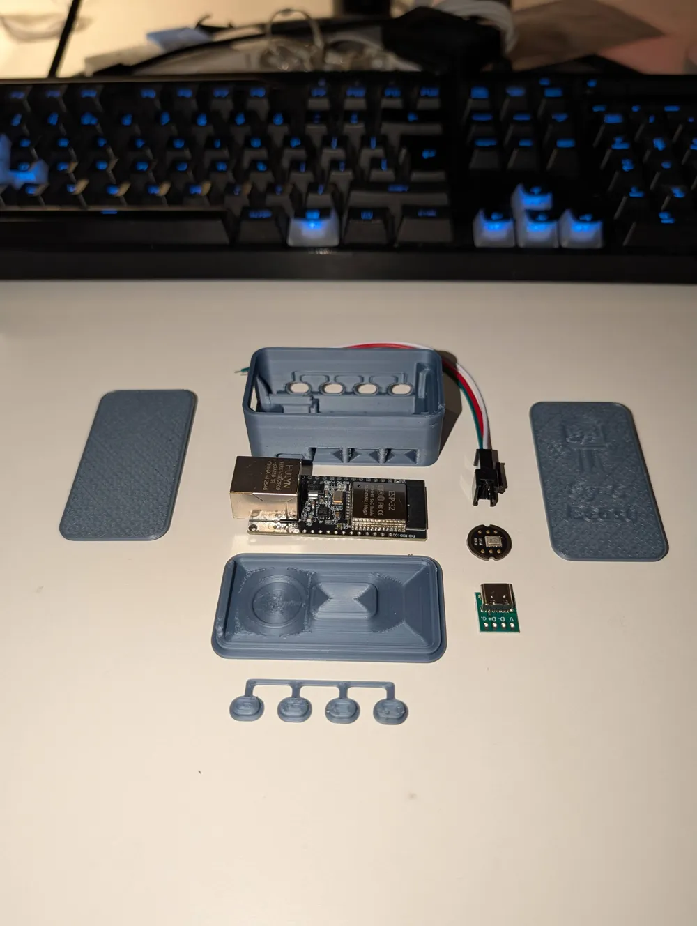
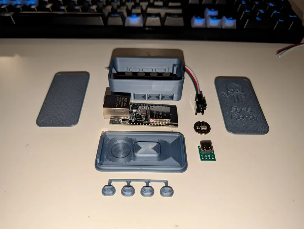
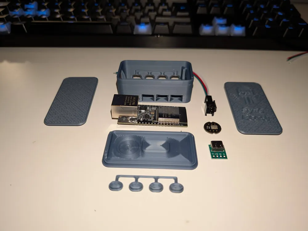
Print Profile(1)

Description
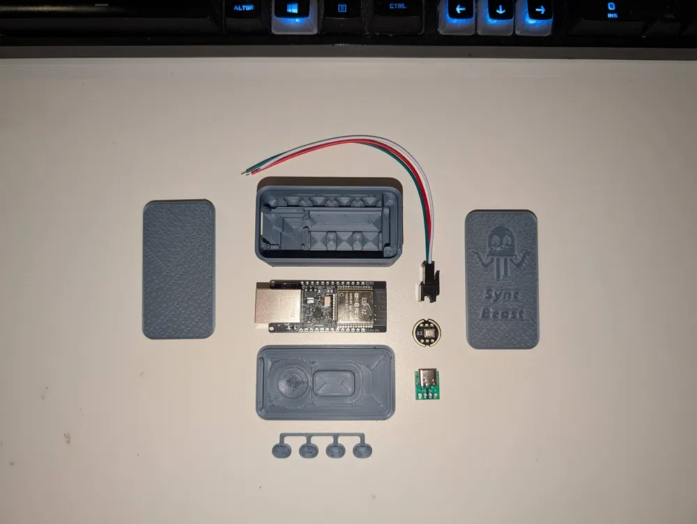
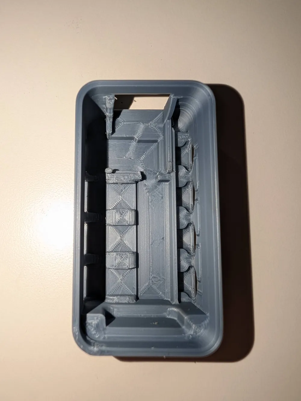
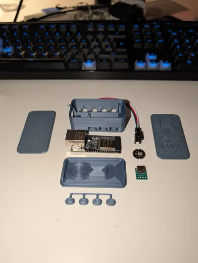
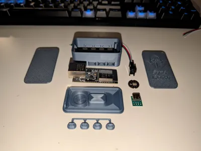
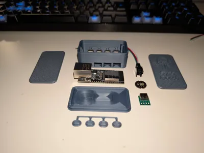
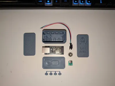
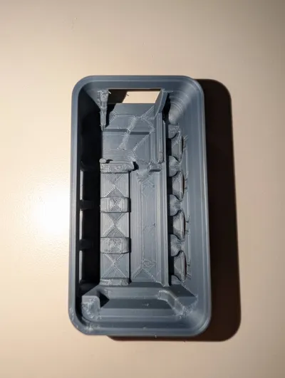
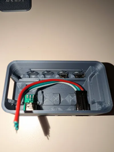
Here is my Quick Design for an Esp32 Ethernet case to be used with WLED.
Warning! please cut the ethernet pins on the back flush of the esp32 board and put a piece of tape over it, or youll fry the ethernet chip on it!
A few notes:
The buttons are hard to go in, this is by design so they dont fall out, youll get it, trust me.
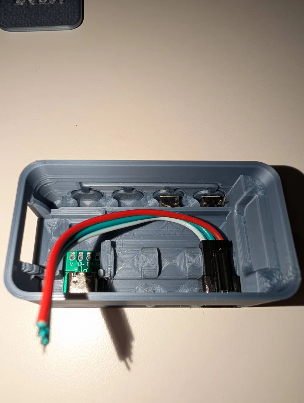
The JST connectors are also hard to go in, they need to be pushed all the way back to their holders, when you get it you feel a snap.
The Usb C board goes in at an angle, then slides forward.
The esp32 Ethernet Goes in last, with the ethernet port going in first, then the module slides back into its mount, and it then gets held in place by the raised area on the lid.
Everything but the usb c board should be glueless, I got lazy so use any glue you want on the usb c
- First Flash the esp32 ethernet with a serial programmer like any other esp
- I use IO2 IO4 IO12 for the JST connectors
- Then connect all the 5v together, and wire one to the esp32, same with ground
- use IO36 IO39 for the buttons with a 10k resistor to the ground pin next to it (and IO14 and IO15 if you dont install the i2s mic)
- connect the other side of all the buttons to 3v3
- For the i2s microphone, connect BCLK (clock) → GPIO14, WS (word select) → GPIO15, SD (data) → GPIO35, VDD→ 3v3, GND and L/R → GND
- When booting wled the first time you connect to the WLED-AP network which then opens the controls, in the wifi setup you set the option “Ethernet type” to WT32-ETH01
- Under LED & Hardware setup, you add the 3 led outputs with data pins 2,4,12
- IMPORTANT DONT SET THE BUTTONS TO PUSHBUTTON ONLY OR THE BOARD WILL NOT BOOT
- Under LED & Hardware setup, you add the buttons on pins 36 and 39, and set the buttons to Pushbutton Inverted
- I also like to set default transition time here
- Then set up the i2s mic (im too lazy to explain, ask grok)
- Then connect an ethernet cable and reboot the board
Esp32 Ethernet Module:
https://aliexpress.com/item/1005006866316794.html
Standard 3pin Adressable LED JST Connectors that you commonly get from aliexpress:
https://aliexpress.com/item/1005007059995763.html
USB C board:
https://aliexpress.com/item/1005010210331301.html
6x6x4.1 DIP Push Button:
https://aliexpress.com/item/1005001629177989.html
i2s Mic if you want audio reactive (Keep in mind you snap the ethernet port pins on the bottom of the pcb to not short out the mic against them)
https://aliexpress.com/item/1005010338533932.html
License

You may create derivative works based on this object, provided that all such derivative works are published exclusively on the MakerWorld platform and include proper attribution to the original creator. You may not share, upload, host, distribute, or publish this object—or any derivative work of this object—on any other digital platform, marketplace, or distribution channel. Commercial use of this object and any derivative works is strictly prohibited. This includes, but is not limited to, selling, renting, sublicensing, or using the object in any context in which you receive monetary compensation or other financial benefits.


Comment & Rating (0)