Remote Control for Droid


Print Profile(3)


Bill of Materials


.png)


Description
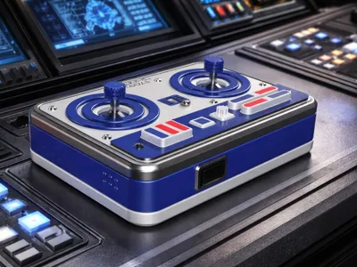
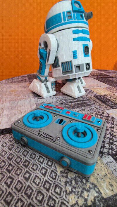
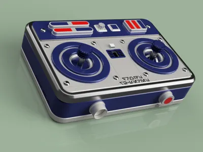
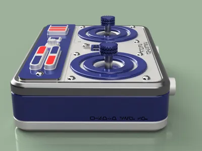
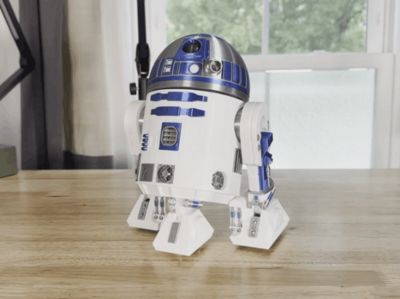
🛰️ Remote Control for Droid (CyberBrick Edition)
After building #Neebick's incredible astromech, I felt the standard controller didn't live up to such an iconic design. That’s why I’ve designed this themed controller from scratch, integrating the Bambu Lab CyberBrick Kit components with the industrial aesthetic of a galaxy far, far away.
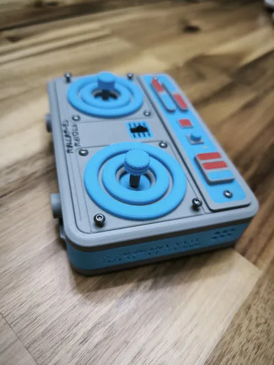
🕹️ Control Configuration
The design is intuitive and makes the most of the CyberBrick modules:
- Right Joystick (Dual-Axis): Full movement control of the droid in all directions.
- Left Joystick (Single-Axis): Precise head rotation (360° in both directions).
- Center (Power Switch): Main ON/OFF switch.
- Rear (3-Position Rocker): Selector to toggle between three programmed light sequences. The center position turns off all LEDs.
- Important note: I’ve attached a specific (.JSON) file for the CyberBrick configuration. Since it uses only one joystick to control the droid, the setup is different from the standard one, both for the transmitter and the receiver.
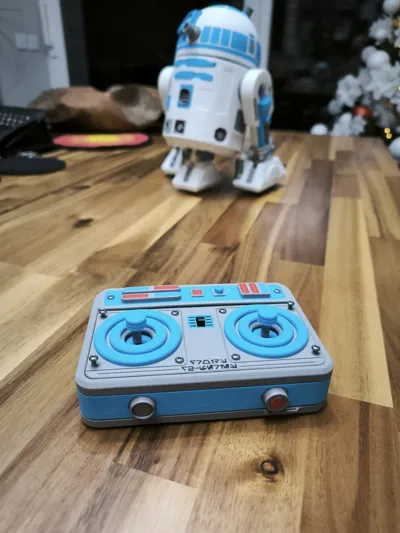
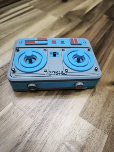
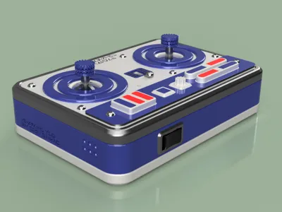
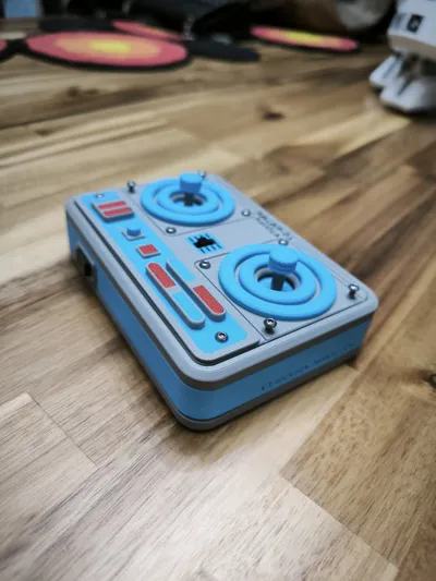
🖋️ Aurebesh Details
For an authentic touch, the controller includes engravings in Aurebesh (the Galactic Basic alphabet):
- Top Cover: "Droids R2-Series"
- Right Side: "W-SOTO ENG. CO." (A nod to custom engineering).
- Left Side: "CB-SYSTEM v1.0 / 2.4 GHz / BT-LINK." This refers directly to the CyberBrick ecosystem, hardware version, and wireless protocols.
🛠️ Print & Assembly Optimization
As a designer, I’ve optimized the model focusing on the efficiency of our machines:
- Filament Saving: I split the top cover into pieces by color. By printing the visible face down on the heatbed, we not only save material and time (avoiding constant purges/poops), but also achieve a spectacular surface finish. Only two pieces require actual color swaps.
- Minimal Supports: Only one part requires supports, and they are designed for effortless removal.
- Hardware: If you only have one CyberBrick kit and you used it to build the droid, you will need an extra battery and an on/off switch.
- Screws: Only 4 screws are functional; the rest are "greeblies" (decorative) to add a realistic touch.
🛠️ Verify Results (Bambu Studio)
I’ve included a .3mf file of an assembled controller so you can experiment with the aesthetics before manufacturing.
- Look for the file: Full Body Color Testing DO NOT PRINT.3mf in the download options.
- Use it in Bambu Studio to test color combinations instead of guessing the final result. It is for visualization only, not for printing.
🛠️ Modifications to the Original Model
One modification I made regarding #Neebick's original model is the head rotation. The issue with using the Bambu Lab Positional Servo is that it's electronically limited to approximately ±45º (≈90º total). On the other hand, the Continuous Servo has no limits and can damage the cable if it rotates multiple times. However, the Continuous Servo is the best choice as it is:
- Silent
- Smooth
- Stick-controlled → speed and direction
- Includes a central deadband to avoid jerky movements.
- Speed limiter to prevent "whiplash" motion.
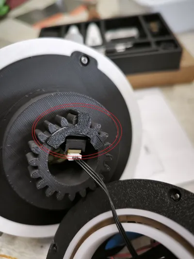
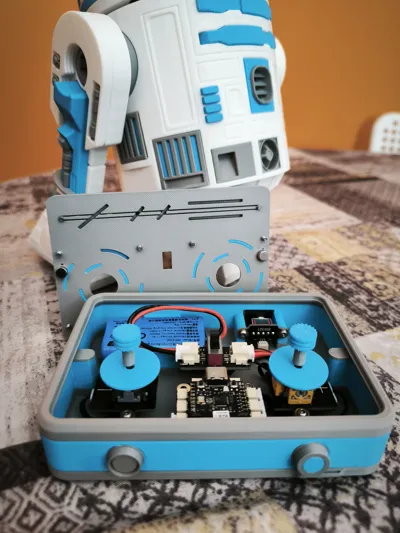
Since the servo does NOT bear weight (it only pushes), I designed a physical mechanical stop to do the heavy lifting. This is a small piece that must be placed on the head gear, specifically between the WS2812 LED Hub with 3-Pin SH1.0 Connector. Please refer to the photos for the exact positioning.

🚨 UPDATE: V2.0 - Magnetic Quick-Access Upgrade! 🧲
Say goodbye to tools just to swap the battery! I have completely redesigned the controller base so you can access the electronics instantly.
If you have already printed the previous version, great news: You do not need to reprint the front cover. I have maintained 100% backward compatibility so you only need to print the new base.
🌟 What’s New in V2.0?
- Magnetic Closure: No more unscrewing the case every time the battery dies. The cover and the base now snap firmly together using 4 magnets.
- Monoblock Design: The three separate parts that used to form the base are now printed as a single object, adding robustness and simplifying the printing process.
- Encapsulated Magnets (Base): The base features internal slots designed to house two magnets. By using a paused print, the magnets end up completely hidden and protected inside the plastic body.
- Decorative Screws: The 10 screws on the front cover no longer serve a mechanical purpose; they are now purely a cosmetic and industrial detail to preserve the droid's original rugged aesthetic.
🛠️ Hardware Required for V2.0:
- 4x Neodymium Magnets: 6 mm diameter x 3 mm thickness.
- A few drops of CA glue (Super Glue).
🖨️ Printing & Assembly Instructions (V2.0)
- Pause for Magnets in the Base: The print file already includes a programmed pause right before closing the bridge that covers the magnet slots.
- Insert Magnets: When the machine pauses, simply place the two magnets into their corresponding slots (polarity doesn't matter here). Resume the print so they get fully encapsulated by the plastic.
- Perfect Cover Alignment & Gluing: Since the original front cover doesn't have specific slots for magnets, we will use magnetism itself to align them perfectly:
- Place the other two loose magnets on top of the printed base (they will automatically snap into place over the hidden internal magnets).
- Apply a small drop of super glue onto the exposed top face of these magnets.
- Place your front cover on top in its correct position, press firmly, and let it dry.
- Once separated, the magnets will remain fixed to the cover in the exact spot and with the perfect polarity.
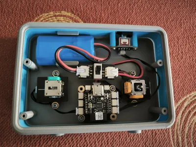
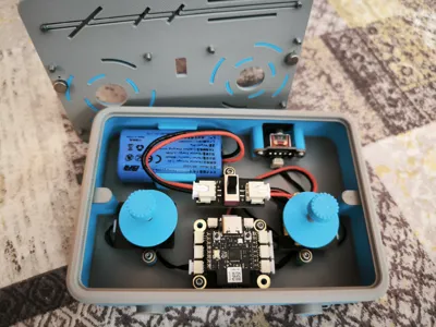
🧠 Expert Tip for Cyberbrick Assembly
To avoid fighting with wires and tight spaces inside the controller casing, strictly follow this order:
⚠️ RECOMMENDATION: Assemble all Cyberbrick electronic components first OUTSIDE the controller. Once you have a compact, pre-wired block, slide it into the base and secure it with the screws, always starting with the rear switch. This ensures everything fits perfectly on the first try without straining any connections.
(Note: I have left the original V1 files with functional screws in a separate section in case anyone still prefers the traditional fastening method).

Comment & Rating (101)