
Raspberry Pi 5 Portable Enclosure
Print Profile(1)

Description
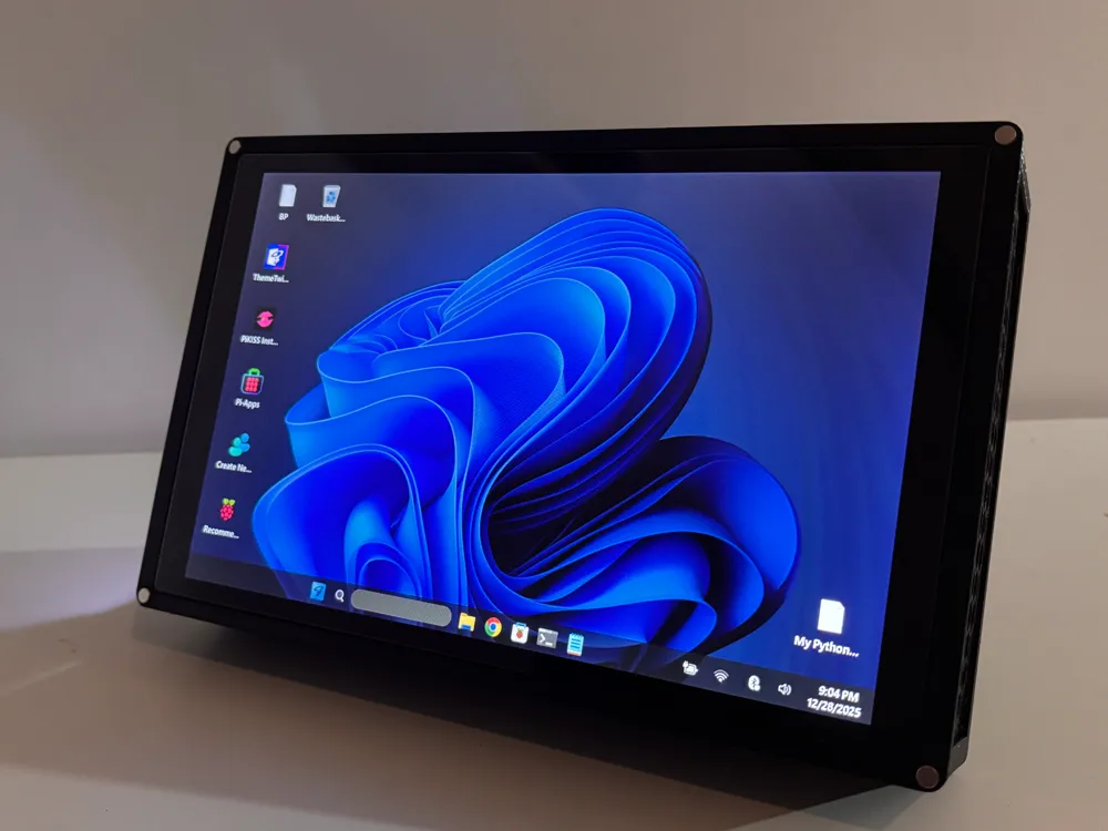
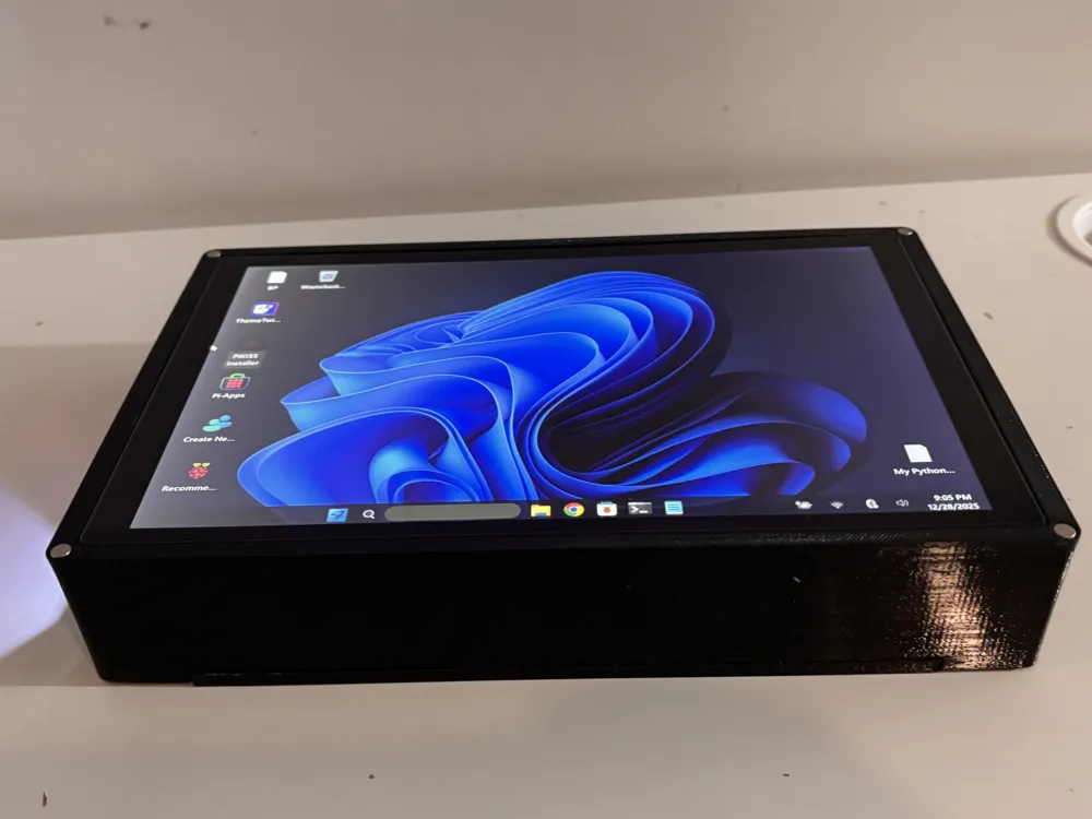
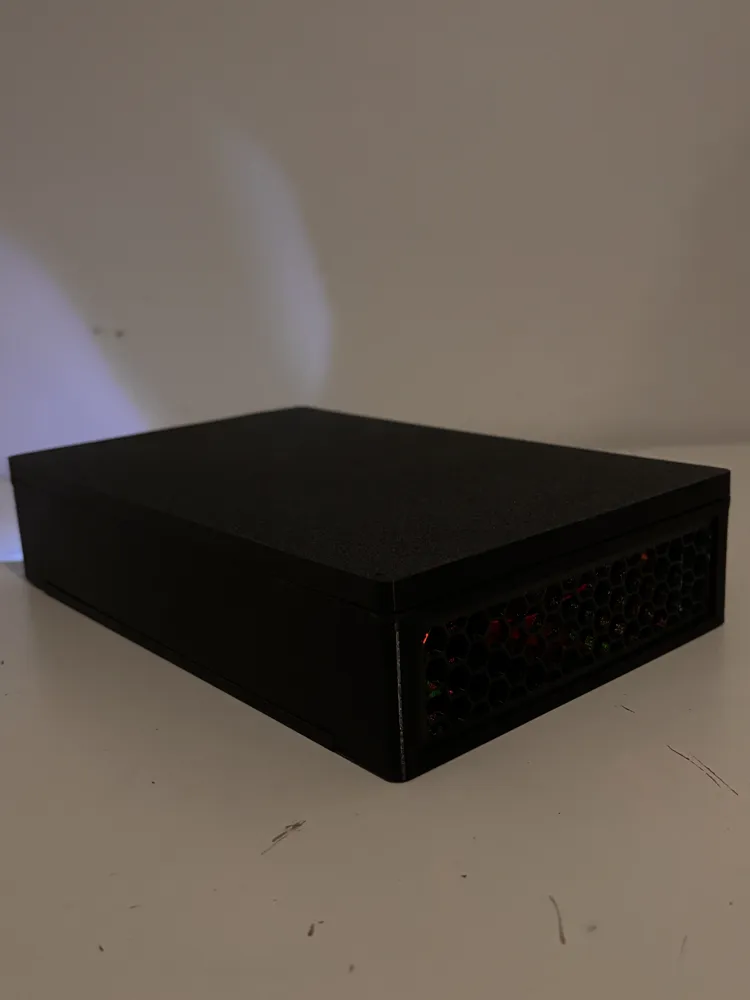
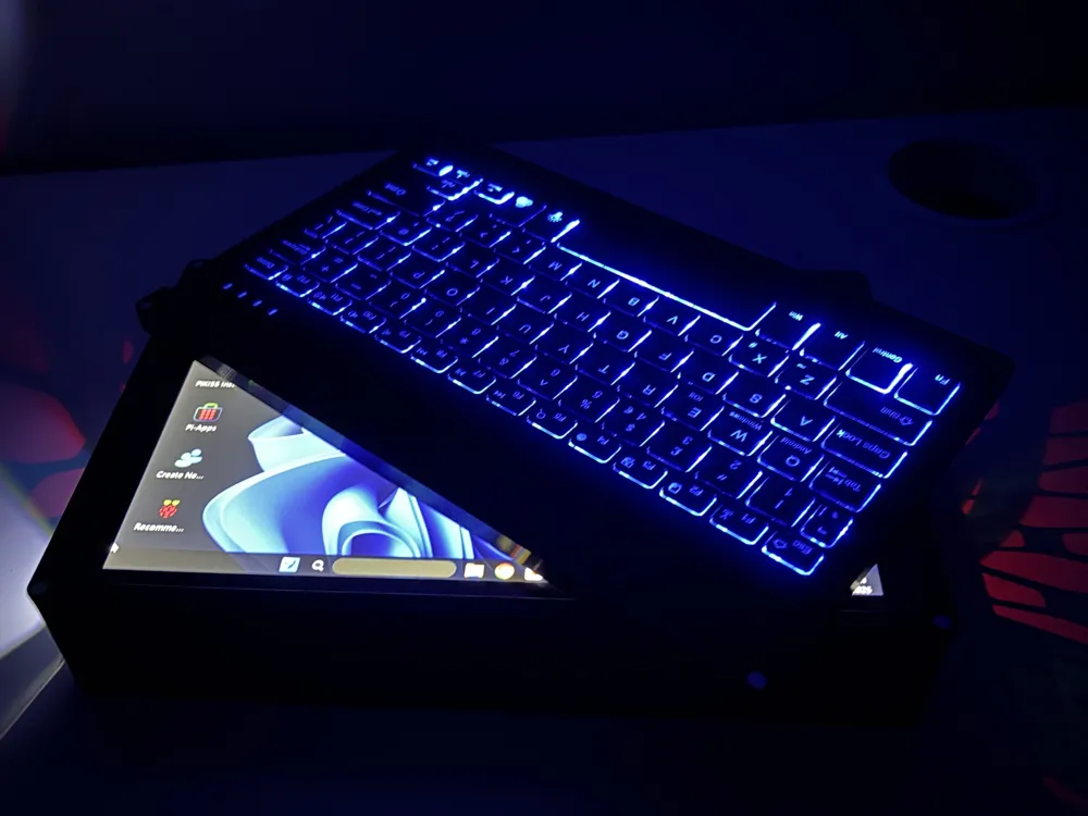
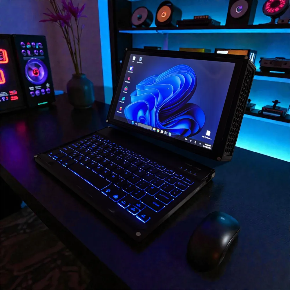
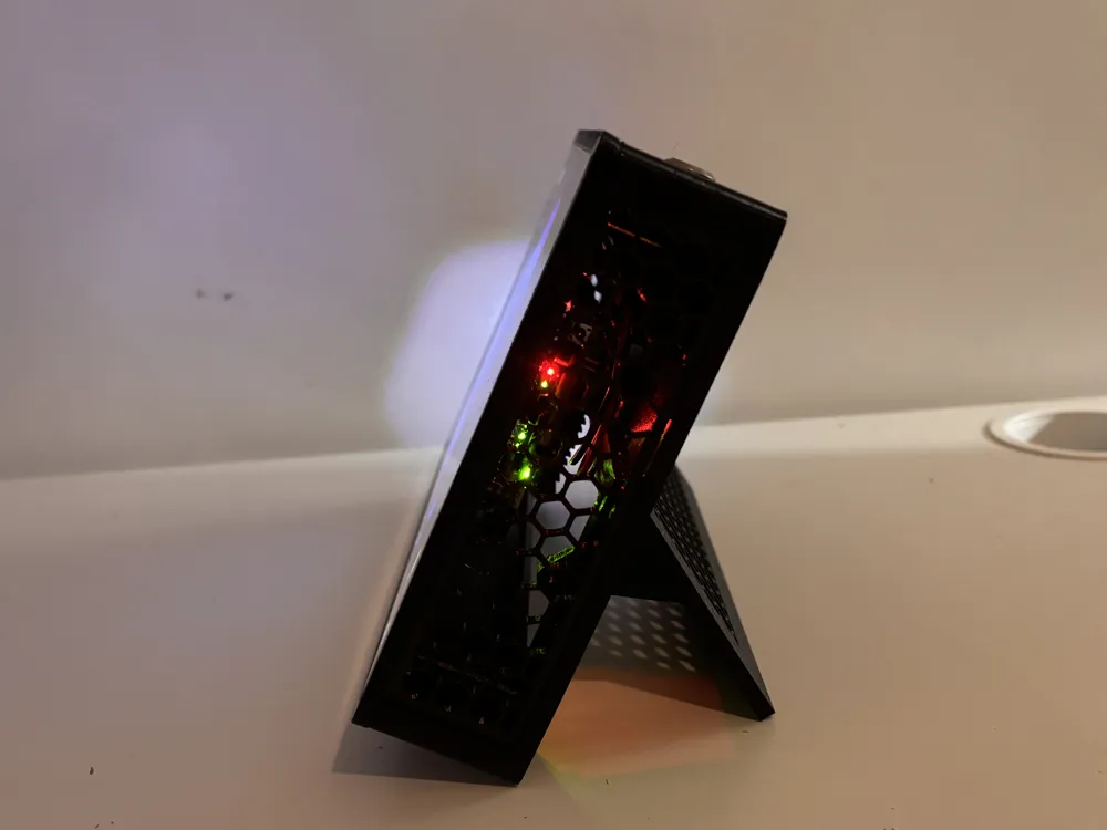
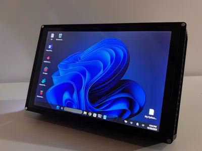
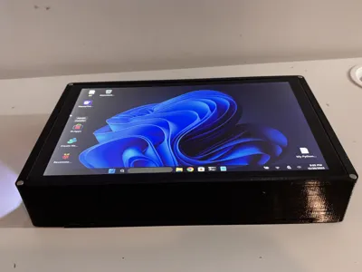
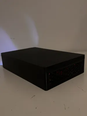
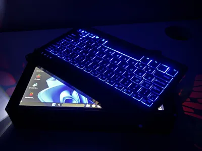
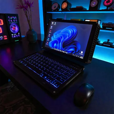
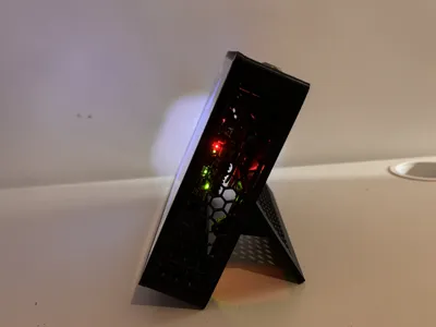
A fun compact Raspberry Pi 5 enclosure designed for the 10.1" GeeekPi touchscreen and UPS X1203. Snap‑fit panels, magnetic mounting, and a 3D‑printed kickstand bolt make this a simple, strong, no‑solder portable workstation.
Materials
- PETG Black Filament
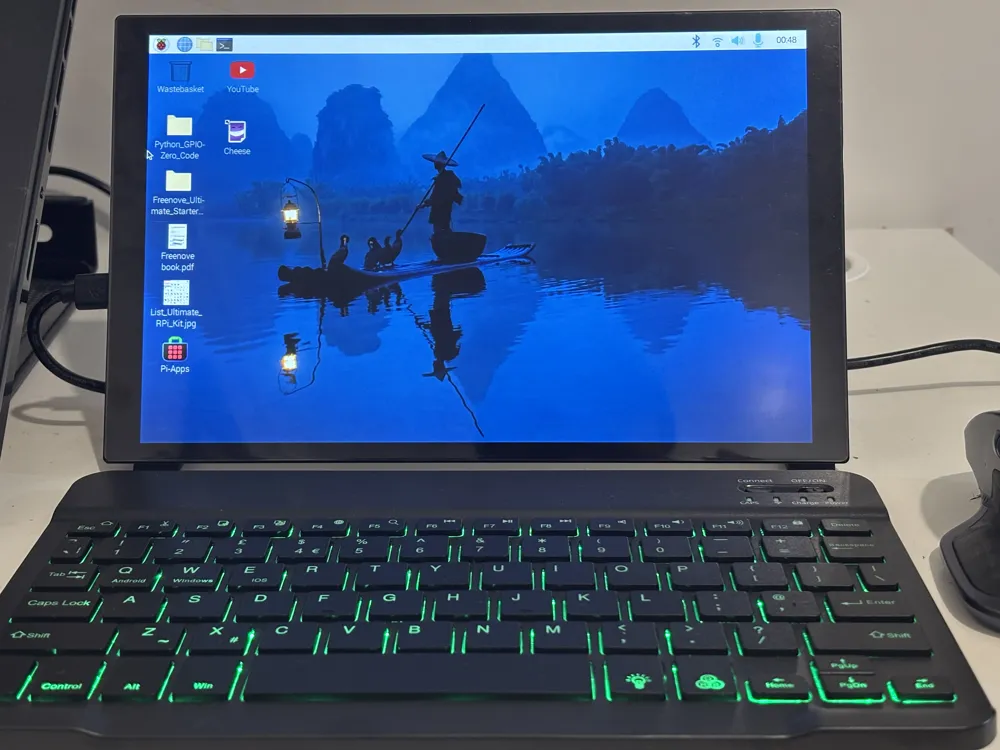
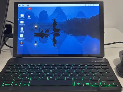
- Bluetooth Keyboard
- GeeekPi Touch Screen 10.1
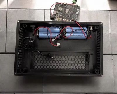
- Geekworm UPS X1203
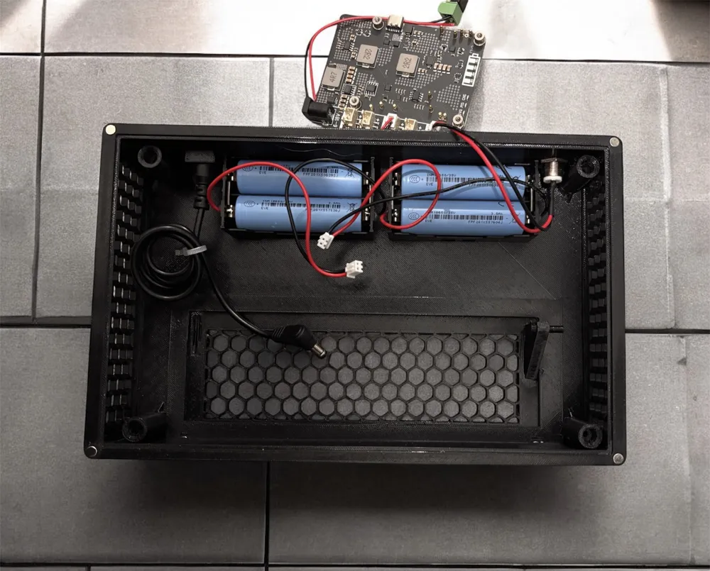
- Geekwork 18650 Parallel Battery Pack ×2
- Geekworm Metal Power Switch
- 18650 Batteries ×4
- Type‑C Terminal
- JST XH2.54 Connectors
- U‑Shape HDMI Mini → HDMI
- U‑Shape USB‑C → USB‑C ×2
- USB‑A → USB‑C Short Cable
- Male–Female DC Extension Lead (Short)
- L‑Shape Micro‑HDMI → HDMI
- HDMI Male → HDMI Male (Short)
- Raspberry Pi 5
- AC/DC 12V 5A Power Adapter
- TP‑Link USB Bluetooth UB5A
- Magnets 5×3 mm (strong or keyboard will slip easily)
Print Details
- Auto supports required for case.stl
- PETG only (strength + heat resistance)
- 0.4 mm nozzle
- 0.2 mm layer height
- No AMS required
Case Assembly
- Hot‑glue both case halves onto the main body at the top middle
- Snap in side hex panels (superglue if needed)
- Snap in the kickstand
- Insert the 3D‑printed bolt
Keyboard Mounting
- Add superglue to the keyboard mounting area
- Press keyboard into place
- Add light weight on top
- Leave to cure for a few hours
Magnets
- Install magnets on the front of the case, keyboard, kickstand, and rear of the case
- Ensure magnets are strong — weak magnets will cause the keyboard case to slip
- Superglue recommended for all magnet placements
Assembly
- Install the Arctic cooler onto the Pi 5 using new pads + nylon screws
- Mount the UPS X1203 on the back of the LCD
- Place the Pi 5 on top of the UPS
- Secure with 4 × M2.5 screws
Wiring
- Connect both 18650 battery packs to the BAT terminals
- Connect the metal power switch to the SWITCH terminal
- Connect 5V OUT on the UPS to the LCD’s USB‑C power input using JST XH2.54 connectors
- Attach U‑shape HDMI to the LCD
- Attach L‑shape mini‑HDMI to the Pi 5
- Add the short HDMI cable between them (add twists for strain relief)
- Attach U‑shape USB‑C to the LCD
- Connect a short USB‑C to USB‑C cable from the LCD to the Pi 5 for touch input
Screw the case
- use 4 x m2.5 screws to attached the screen to the enclosure
License

You shall not share, sub-license, sell, rent, host, transfer, or distribute in any way the digital or 3D printed versions of this object, nor any other derivative work of this object in its digital or physical format (including - but not limited to - remixes of this object, and hosting on other digital platforms). The objects may not be used without permission in any way whatsoever in which you charge money, or collect fees.


Comment & Rating (6)