Removable Molle Insert, Pelican 1510


Print Profile(2)


Description
YOU CAN PRINT THIS ON A P- OR X- SERIES PRINTER BUT YOU MUST ADJUST THE PRINTER SETTINGS ON YOUR OWN
3 IMPORTANT THINGS TO DO BEFORE PRINTING:
- You MUST use the “no exclusions” profile for you printer to remove the void at the front left corner of the bed (P1S and X1C).
- This can be found here, Makerworld prevents me from uploading that setting in the print profile. Read up on the process so you know what to expect.
- Ensure that your printer is calibrated and the heat bed is clean. Calibration is important because the toolhead must have accurate positioning around the print area. A slight miscalibration can result in the print going off the edge of the bed, I experienced this first-hand. Glue the heat bed if necessary.
- Remove the nozzle load line (first line at the front of the bed) to avoid printing over it for a cleaner print.
------------------------------------------------------------------------------------------------------------------------------------------------------------------------------------------------------------------------
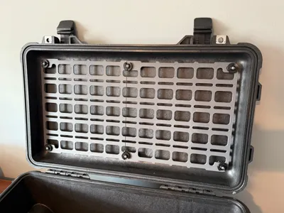
This is a molle insert for the lid of a Pelican 1510 case. I don't think this will fit any other case, but see the attached drawing for the approximate hole spacing.
There are 2 models here, one that is removable and one that is not. All versions use a #6 (3.5mm) self tapping screw to attach to the case.
Removable Panel: This uses 2 different panels that are labeled in the print profile. These overlap each other when installed and stay in place with clips. The pins use screws that are NO LONGER THAN 7/8'' (0.875in or 22mm). The smallest it can be is 5/8'' (0.625in or 16mm) and that works fine. You can use a 3/4'' (0.75in or 19mm) long screw to meet in the middle.
Fixed Panel: This uses the same panel for both sides, they are a mirror image. This panel uses screws that are NO LONGER THAN 3/4'' (0.75in or 19mm). The smallest it can be is 1/2‘’ (0.5in or 13mm). The panels are screwed directly to the case. You should avoid removing this panel too frequently as to avoid wearing out the plastic that the screws are threaded into.
Also uploaded as a STEP file is a blank panel (P1510_BLNK). Please use it to create your own panel with custom hole patterns or profiles. If you do make your own, please upload it as a new print profile, to keep everything in one place.
VISUAL NOTE: In the effort to avoid supports, both panels are printed in the same orientation, but when installed, will be opposite of each other. This leaves two different surface finishes showing when installed. If you are using the textured plate then it is more noticeable. If you want the same texture to show on both sides, then you will have to manually flip the part in Bambu studio and add supports at the overhang. Be sure to clean the supports off very well to ensure a close fit when installed.
Shoutout to @Austin for making me realize I can model and print this. Check out his model for a single panel
Update log:
1/11/26: Added removable panel. Rewrote description to focus around removable panel rather than fixed.
Documentation (1)
License
You shall not share, sub-license, sell, rent, host, transfer, or distribute in any way the digital or 3D printed versions of this object, nor any other derivative work of this object in its digital or physical format (including - but not limited to - remixes of this object, and hosting on other digital platforms). The objects may not be used without permission in any way whatsoever in which you charge money, or collect fees.
Comment & Rating (23)