
AD5X Base with Drawers and Power Routing
Print Profile(1)
Bill of Materials
- Lighted Switch x 1: Lighted DPST Rocker Switch
- Male Plug x 1: Screw Mount 3 Pins IEC320 C14 Inlet Power Plug
- Female Plug x 1: 3 Pins US Power Socket Plug Panel Mount
- Wire x 1: 18 awg minimum, 14 awg or better recommended
- spade terminals x 1: To connect wires to the terminals on the switch and plugs
Description
06/02/2026 Update - I recut the files as it looks like in my tinkering I lost pin pieces. The new print profile has them all but you will want to reorient the pieces to suit your needs. I am also adding the uncut full drawer STL in case you want to cut it yourself.
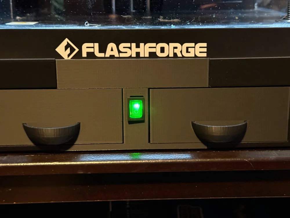
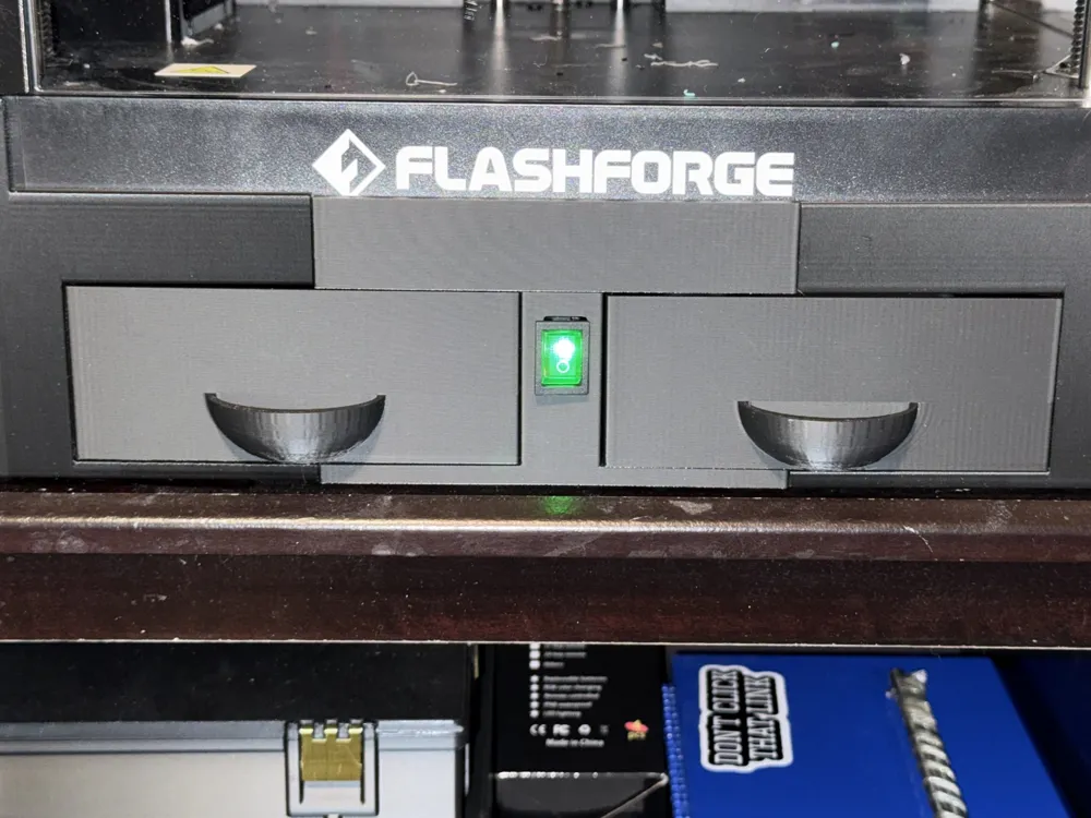
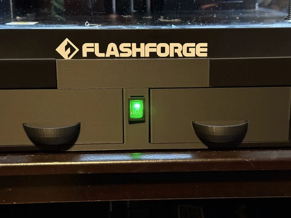
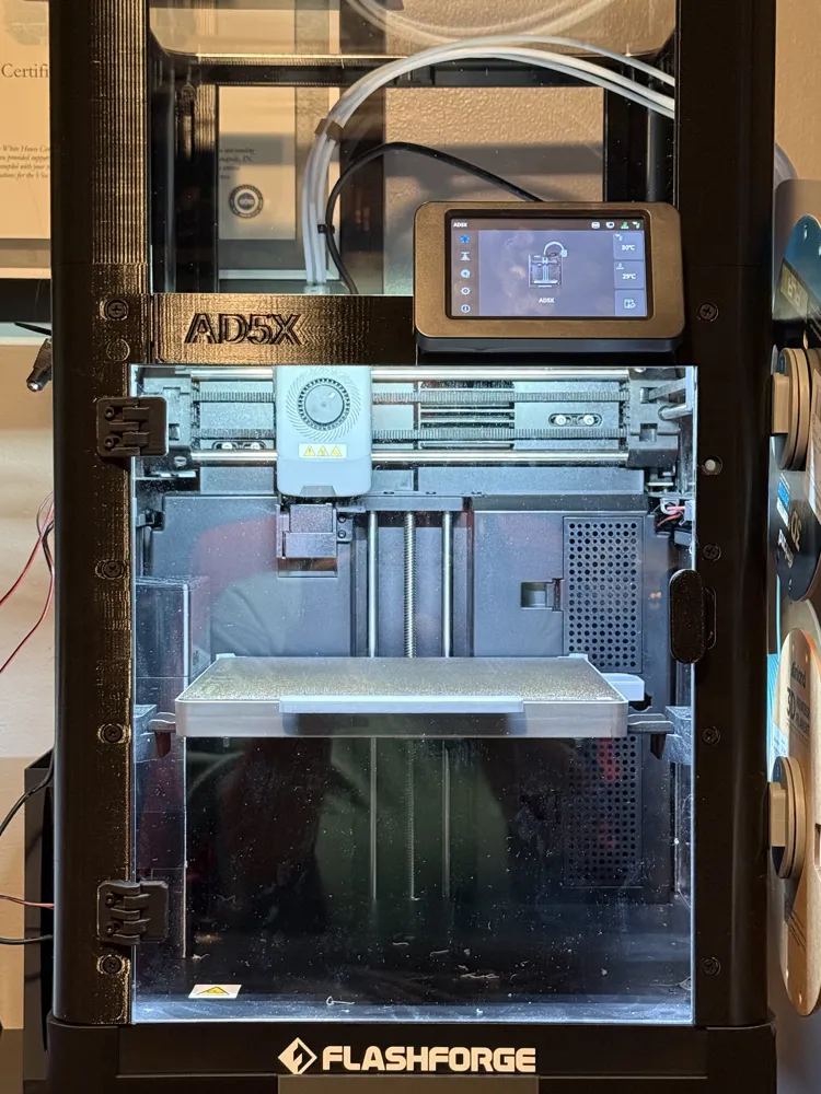
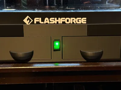
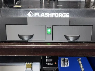
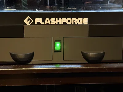
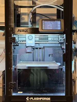
I wanted a base for my AD5X that would route the power switch to the front of the printer and add storage for tools. I wanted a lip around the corners of the printer to help ensure the printer did not wobble off, but I wanted to retain access to the lift points on the front, the connections on the back and the FlashForge logo on the front. This checks all of those boxes for me.
The file has the base split into six pieces using dovetails to connect the three front pieces as well as the three back pieces. The assembled front and back halves have alignment pins to help, but you will want CA glue to permanently join them.
I used 3 walls for the main body pieces and 10% gyroid infill with a .28 layer height. I printed it all in PLA.
For the electrical hookups, I used:
https://www.amazon.com/dp/B07QS9QLB1
https://www.amazon.com/dp/B092VQNKN7
https://www.amazon.com/dp/B01N2T2N1W
A terminal set for spade connectors and 14 gauge wire. 18 gauge is what came prewired to my plugs, but 14 gauge would be better, which it is what I had and seems to be doing just fine.
License



Comment & Rating (51)