Search models, users, collections, and posts
Nema 24 peristaltic pump
IP Report


Print Profile(0)
Add the first print profile to earn points
Boost
11
28
0
1
2
0
Released
Description
Peristaltic pump for a NEMA 24 stepper
The project is at proof of concept stage, to demonstrate how a peristaltic pump works. I've built it and it works but feel free to remix the design if you have any ideas how to improve it.
The Good bits:
- Fluids can be pumped without touching anything other than the tube
- Pressure is good
- Capable of flow rates > 3L/min
The Bad bits:
- 3D printed threads are poor, the glands are hard to get started
- Requires additional parts - see parts list
- Noisy
- Supports are required - designed for PETG with a PLA interface layer
Flow Rate tests (approximate):
100rpm = 0.75L/min
200rpm = 1.5L/min
400rpm = 3L/min
These test were all conducted by timing how long it took to drain a 0.5L container of cold water. I have not conducted any maximum speed tests and have no idea at what speed things break apart or how speed affects tube wear.
WARNINGS:
- Use at your own risk.
- Risk of injury, only enable the motor when the housing is fully assembled and the lid is fitted and secured.
- This type of pump is not intended to run at high speed.
- The pump may fail violently, ensure it cannot cause harm if parts are ejected from the housing.
- Do not use in application where failure of the pump risks injury or damage.
- When inserting the tube ensure the motor is isolated and turn the rotor by hand.
- The nature of the pump means the silicone pipe is repeatedly crushed, inspect regularly and replace before failure.
- The pump is designed for printing in PETG, ensure the material you use is suitable for the temperature of the liquid you are pumping.
Build Instructions:
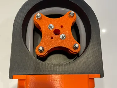
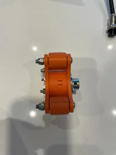
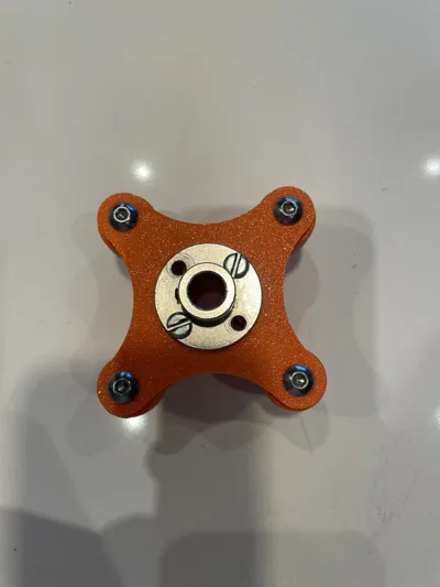
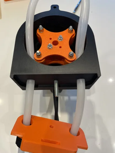
- Clip the two halves of the rotor together and pass bolt [F] through the flange coupling and both halves of the rotor. The head of the bolt should be on the flange side of the rotor. Fit the washer and nut and tighten until the assembly is secure.
- Remove the support material from the rollers and press in a bearing [C] into each end of each roller
- Fit the rollers into the rotor using bolts, nuts and washers [E] and tighten until the roller is secure, but not so tight as to prevent it rotating. The heads of the bolts should be on the flange side of the rotor.
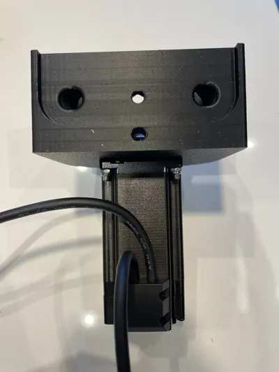
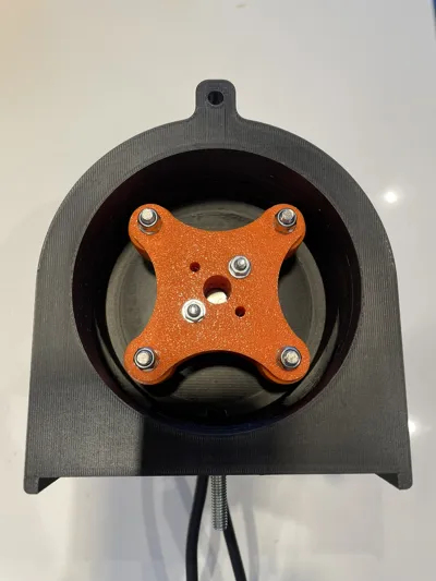
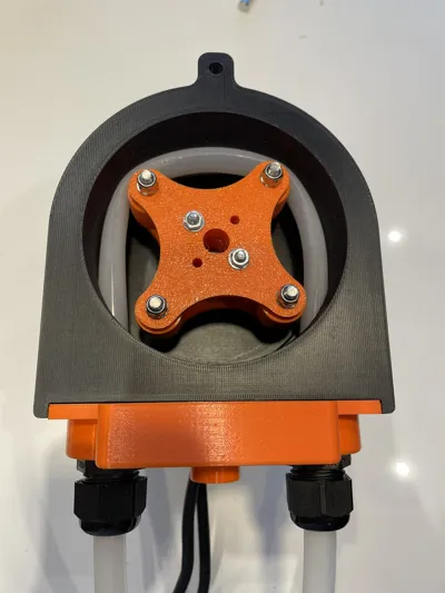
- Fit the housing to the motor using bolt, nut and washer [G]. The head of the bolt should be on the housing side.
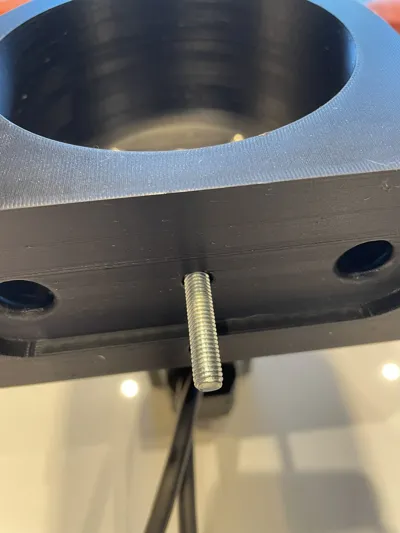
- Insert the bolt [I] into the hex shaped hole in the side of the motor housing. the bolt should be inserted so the thread extends through the housing.
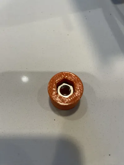
- Press the nut [I] into the hex hole of the small round printed piece. Thread onto the exposed thread from the previous step and tighten to put the nut and bolt into place. Then unscrew the round piece with integral nut and put to one side
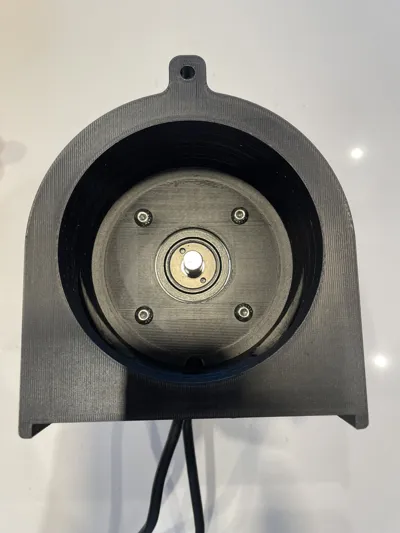
- Rotate the motor shaft till the flat side faces the flat side of the housing with holes in.
- Slide the coupling [D] over the motor shaft, line up the grub screw with the flat side of the shaft. This can be tightened using the hole in the side of the housing. Ensure the rotor is far enough down in the housing so the exposed threads of the rotor bolts are below the top edge of the housing to prevent them rubbing on the lid.
- Remove the support material and insert the cable glands [J] in the gland plate. If you can't get the tread started try snipping a small (2mm) cut in end of the thread to allow it to reduce in diameter
- Feed the pipe [B] though one gland, into the housing and out of the other gland. Rotate the motor by hand (ensure the motor is disabled) while feeding the pipe in between the rollers and the wall of the housing. The pipe should sit on the middle of the rollers.
- Loosely tighten the cable glands so the pipe is secured but not crushed
- Refit the small round 3D printed piece onto the exposed thread and tighten, finger tight to retain the gland plate
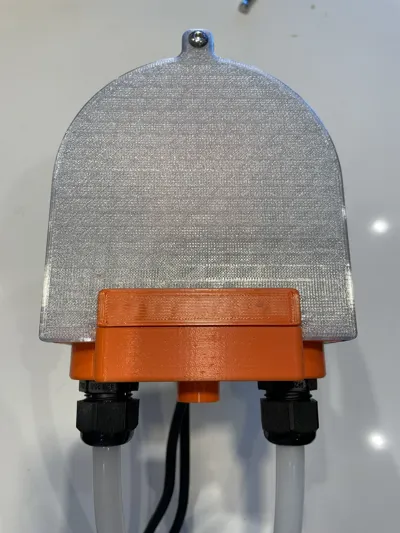
- Slide the lid into place and fit nut and bolt [H] through the hole at the top of the lid and housing
Parts List::
- Nema 24 stepper motor + driver + controller
- 8mm ID /12mm OD silicone pipe (if you use another pipe size you may have to adjust the rotor size)
- 8off - 5mm ID/10mm OD bearings (4mm wide)
- 1off - 10mm flange coupling (to connect the rotor to the stepper motor)
- 4off - M5x40mm button head bolt + washer + nyloc nut (to act as a shaft for the rotors)
- 4off - M3x40mm button head bolt + washer + nyloc nut (to attach rotor to flange coupling)
- 4off - M5x20mm button head bolt + washer + nyloc nut (to attach pump housing to motor)
- 1off - M5x20mm button head bolt + washer + nyloc nut (to attach lid to pump housing)
- 1off - M6x25mm hex head bot + nut (to create locking mechanism
- 2off - M20 nylon cable glands (to hold the pipe in place)
License
This user content is licensed under a
Creative Commons Attribution-Noncommercial-Share Alike
Comment & Rating (0)