Model of an electronically controlled coupling


Print Profile(6)


Description
*Note;
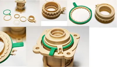
The models introduced here are as follows:
- Coupling
- Parts for connecting the coupling to the differential unit
The differential gear has been uploaded separately, so please refer to that as well.
------
The electronically controlled coupling is a device that automatically adjusts the distribution of drive force to the front and rear wheels according to the vehicle's driving conditions. The ECU (Electronic Control Unit) analyzes various sensor inputs such as vehicle speed, accelerator pedal position, steering angle, and wheel slip, then controls the hydraulic pressure and magnetic force within the coupling as needed. This allows for increased rear-wheel drive force on slippery surfaces to enhance stability, while enabling fuel-efficient 2WD-like operation during normal driving.
Compared to conventional mechanical 4WD systems, electronically controlled couplings offer higher responsiveness and superior fuel economy by suppressing unnecessary torque transfer. They are widely adopted in many current AWD (All Wheel Drive) vehicles, serving as a technology that balances stable driving performance with efficient drive force control.
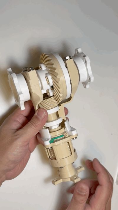
This 3D model is a movable replica of the drive force distribution mechanism found in actual representative models.
For ease of use as an educational model, electronic components have been omitted.
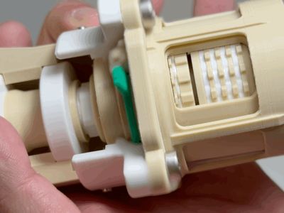
A key design feature is the use of permanent magnets and mechanical mechanisms to replicate the operation of an electromagnet, allowing the clutch strength to be adjusted.
To ensure smooth operation, you'll need to file the parts so they fit together properly.
This requires careful work. Have tweezers ready for assembly.
Those with patience are encouraged to try making it.
Other parts to prepare
*Addendum: The threads are quite tight, so we recommend using metal screws.
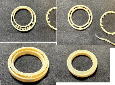
- A 3mm diameter Stainless steel ball = 47pcs
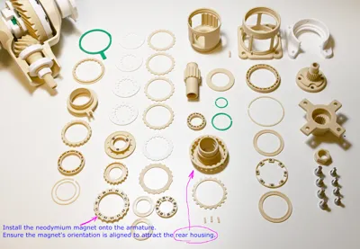
- Neodymium magnets, 3mm diameter, 2mm thickness = 28pcs or 1mm thickness = 56pcs
- Orient the magnets so the armature and rear housing attract each other magnetically.
- Low-profile(2.7mm) M4 L10 metal screws = 4pcs
- M5 L10 metal screws = 4pcs
- M2 Self-tapping screw = 2 - 3 pcs. Select the appropriate screw size for connecting to the differential.
- The rear housing is printed in three separate pieces. Adhesive is required for assembly.
When connecting to differential gear models using screws, replacement parts for connection and drilling holes in the differential gear model are required.
License
You shall not share, sub-license, sell, rent, host, transfer, or distribute in any way the digital or 3D printed versions of this object, nor any other derivative work of this object in its digital or physical format (including - but not limited to - remixes of this object, and hosting on other digital platforms). The objects may not be used without permission in any way whatsoever in which you charge money, or collect fees.
Comment & Rating (1)