Cylindrical Cam - Educational model


Print Profile(2)


Description
My Educational Mechanical Examples Series
This model is one of my educational mechanical mechanism examples on 80mm x 80mm base plates.
You can find all models of the series in this collection => [Mechanical Mechanism Examples]

The present model
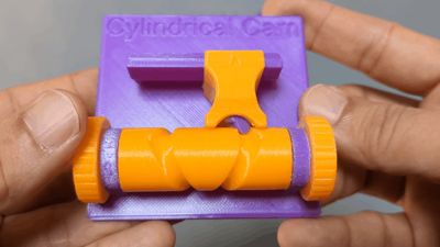
This is an educational model of cylindrical cam, where the follower makes one back-and-forth stroke at nearly constant speed for every two rotations of the cam.


Brief Description
A cam changes the position of a follower as it rotates, and by designing the cam profile appropriately, the follower can be made to follow almost any desired motion.
In a plate cam mechanism, the follower moves perpendicular to the cam’s rotational axis, whereas in a cylindrical cam mechanism, the follower’s motion is parallel to that axis.
In this model, the cylindrical cam is a type of groove cam, where the follower is constrained by a groove-shaped track.
As in my educational model of a plate groove cam, the cam profile here consists of a single continuous groove that winds around the cylinder twice, causing the follower to make one reciprocating stroke for every two rotations of the cam. Because the groove makes two full turns, the path intersects itself at one point. To prevent the follower from entering the wrong branch at the intersection, the follower is given an elongated shape and is free to rotate as it moves along the track, ensuring that it always follows the correct path.
In this model, for 3D-printer-friendly design, the groove uses a cylindrical (rounded) cross-section instead of the usual rectangular profile.
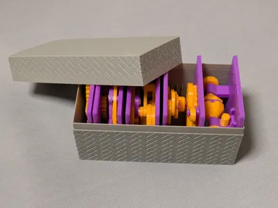
Case
This model is compatible with the case included in my first set.

Printing
- Use the models named ???-printable.stl for printing.
The models named ???-assembled.stl are provided just to show how they should be assembled.
- Use well-dried PETG to have better dimensional accuracy.
- Use 0.1 mm or 0.08 mm layer height to have smoother surfaces.
- Use slow printing speed for overhangs.
- Select “Random” seam position to have smoother rotation.
Randomly distributed seam should be easily worn out after some wearing.Printing
Sanding and Filing
Note that, in this model, the rotation of the bases for bearings is intentionally made not too smooth.
Sometimes, the gears suffer from the stringing effect and/or elephant foot effect, resulting in a too tight fit to the shafts (they are designed with a 0.15 mm radial clearance).
If you see rough surface on the shafts due to stringing, sand off the roughness with a small piece of sand paper.

If you feel the gears do not rotate smoothly due to an elephant effect, widen the hole slightly by using a thin round bar file.

Without those issues, the parts should rotate very smoothly with minimal friction.
Assembly
Place the follower, then place the cam. Finally, insert the handles from the both sides.
Note that the shaft of the handle has a flat.
So, when inserting it into the hole on the cam, the flat must be aligned with the flat inside the hole.

Other examples
You may also be interested in the models in my educational mechanical mechanism examples.
Find them in this collection:
https://makerworld.com/collections/15048577-my-educational-mechanism-models
Happy printing!
Acknowledgement
I got into gears thanks to K.$uzuki's amazing articles and YouTube videos. Many of the mechanisms shown in this series came from the introductions on his website. He also makes excellent gear models himself. This series wouldn’t have existed without his inspiration.
I learned a lot about technical detail of designing gear tooth profiles from Haguruma-No-Hanashi website. I’m truly grateful for that.
License (2026-03-13 updated)
- The 3D model(s) are licensed under Creative Commons Attribution 4.0 International. (unchanged)
- However, the text and images on this page are copyright reserved. (added on 2026-03-13)
Comment & Rating (1)