Raspberry Pi Relay Module Enclosure


Print Profile(1)

Bill of Materials
- RPI relay module x 1: similar to JESSINIE - ASIN B0CDH1L58X
- 110V grounded receptacle x 3: similar to weideer - ASIN B092VQNKN7
- circuit breaker/thermal reset x 1: similar to mxuteuk - ASIN B08QVHQ5WR
- strain relief x 1: similar to Mozeat Lens - ASIN B0CX8759Y1
- 40 pin GPIO extension cable x 1: similar to jujinglobal - ASIN B09K6FF6PR
- M2.5 x 3.5 x 4 heat set threaded insert x 8: similar to HANGLIFE - ASIN B0CS6YVJYD
- suggested: crimp ferrules x 1: if needed a kit similar to Fidioto - ASIN B0D14KBWN2
- suggested: crimp end caps x 1: if needed assortment similar to woshilaoDS - ASIN B0BX9QTTWZ
- M2.5 x 20mm hex spacer/standoff x 1: if needed assortment similar to Geekworm - ASIN B0756CW6Y2
Description
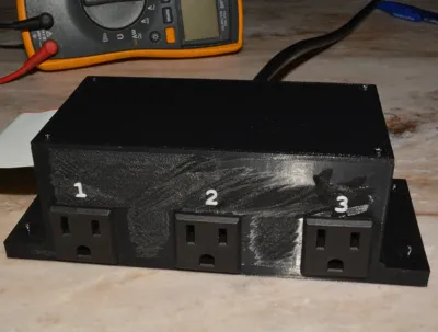
Use this enclosure for an outboard RPI Relay Module connected via a 40-pin GPIO cable.
Cutouts are provided for three snap in 110V convenience (US standard grounded) outlets, a standard strain relief and circuit breaker.
The hole for the strain relief will accommodate cable with 16 gauge wiring which provided you keep the cable length to a meter or less is adequate for 15 amps of current. The 18 gauge wire I used is rated for 10A at the same length and is the rating of the circuit breaker.
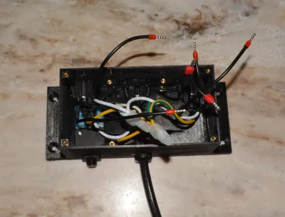
I highly suggest that you make use of the crimp on ferrules for the relay contacts as shown. They make an excellent, best practice connection regardless of the wire type. The convenience outlets used here have individually tinned wire in the stranded cables making the ferrules a necessity as tinned wire of any sort tends is not suitable for these connectors. The “wire nuts” are crimp on end terminators.
The heat pressed (a micro butane torch is ideal) holes are sized for M2.5 x 3.5 x 4; the standoffs to hold the circuit board are M2.5 x 20mm. Screws used are 4x M2.5 x 7 and 4x M2.5 x 5
I printed in PETG and the 2mm thick walls seem ideal with components holding (and removing/replacing) securely.
Comment & Rating (0)