Nightstand / Bedside Cabinet / Cabinet - Stackable


Print Profile(2)


Bill of Materials

Description
Assembly instructions at the bottom!
Updates:
- Added .stl files for large printers (H2D, etc.). The base plates/floors can thus be printed as a continuous part if the print bed is large enough. I only have the P1S myself and couldn't test it, so please give feedback if something doesn't work! (each level saves 9x M3 nut + M3x10 flat/countersunk screw and skips step 1)
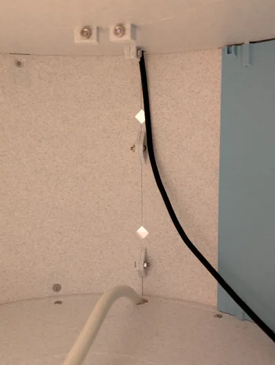
- Openings for cable routing in the base plates opened to the back to facilitate subsequent changes
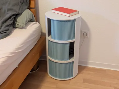
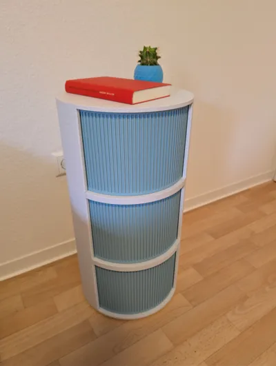
I designed this bedside table, which can be completely 3D printed except for a few screws.
The doors can be pushed open in both directions and run in a guide.
The parts are divided so that they can be printed on a 256x256x256 print bed. Once assembled, the bedside table has an outer diameter of 318mm. The parts can be connected with screws, and the cabinet can be assembled this way. The elements are stackable, and you can build just 2 levels or more.
Inside and on the back there are openings for cable routing, or for attaching mounts (not yet designed).
In the uploaded version, I have already made changes compared to my assembled version: The cable channels have been made larger so that multiple cables can be routed through more easily.
The entire bedside table with 3 levels consumes approx. 2.5kg of material
Required screws / nuts and quantity:
- M3x4 mm countersunk head ISO 10642 (M3x5mm might work better but not tested) - 36x
- M3x8 mm countersunk head - 6x
- M3x10 mm countersunk head - 12x
- M3x16 mm countersunk head - 6x
- Pan head/flat head M3 screws, at least 10mm thread (countersunk head probably also works) - 42x
- Square nut M3 flat (!!) DIN 562 - 54x
- Hex nut M3 - 48x
Please note:
- depending on the material you print this cabinet with, it should not be exposed to strong sunlight, so that nothing deforms.
- this is the first version of the model. The assembly worked quite well for me, but depending on print quality and tolerances, you sometimes have to improvise a bit with the screws. However, I had no problems assembling the cabinet to be functional.
- I have added Brim Ears in several places in the model for improved print bed adhesion. These are not strictly necessary and can be removed if you trust your printer/filament
If anyone has suggestions for improvements, please feel free to write to me. The following ideas are already noted for future models:
- Inductive charging: Cutout/holder in the top level to install an adapter for inductive charging
- Version for large prints: the levels could theoretically be printed as one part on large printers. The corresponding model still needs to be added. (done)
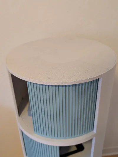
- Different surface designs for the door or the body
- Detailed assembly instructions (done)
For questions or suggestions for improvement, please feel free to write to me!
Instructions:
(first version, I'll try to make a nicer guide sometime, but this should suffice for now)
Connect all floor parts together (left, right, front, and center respectively (for Bottom, only p1 each)) – using M3x10(+) flat head/pan head screws and M3 hex nuts.

- Attach all connectors to the floor surfaces:
Bottom Floor: Place Floor_Bottom_left_p2, Floor_Bottom_right_p2, and Floor_Bottom_front_p2. Then insert 6x Connection_Bottom into the corresponding recesses, place M3 hex nuts into Connection_Bottom from below, and secure with M3x16 countersunk screws from above. If desired, felt glides (d=25mm) can be glued into the 4 recesses at the bottom.

Top floor: Insert flat M3 square nuts into the 6 recesses. Then connect 6x Connection_Top_wall with M3x8 countersunk screws from the side.

Floor 1/ any other level: same procedure as for the Top floor, but with the Connection_wall part on the sides. Pay attention to the orientation! The connector must be oriented with a flat bottom side (as shown in the picture). Otherwise, the walls cannot be mounted.

- Walls:
Place flat M3 square nuts from the outside into the recesses of the connectors (if necessary, fix with a small piece of adhesive tape) and then place the walls from above (make sure the correct wall (top/mid/bottom) is chosen). Then screw them tight from the inside with M3x4. (If the screw does not grip, you can either carefully apply pressure to the nut through the wall, or place something behind the nut so that it is pressed towards the screw. Alternatively, M3x5 screws could be used, these might push through the wall a bit to the outside, so be careful when tightening!)

Once both walls are in place (and if necessary, cables have been routed through the opening), they can be connected at the back with M3 hex nuts and M3x10+ flat head screws.

- Prepare doors:
Insert 8x Slider_insert into the respective recesses of the doors

- Insert the doors onto the respective lower rail. Pay attention to the orientation as shown in the pictures.
- Assembly:
You should now have these elements:

- Stack the elements from bottom to top. Make sure that the sliders of the doors engage with the rail.
- If the doors do not open and close properly, the Slider_inserts must be replaced. Then scale the inserts in the slicer to make them longer/shorter and try again.
If necessary, you can also fix the elements to each other (as with the walls, but on the top side. (I didn't do this, as everything was already stable enough. You just have to be careful when carrying/moving it so that not everything is firmly assembled.)

Finished! If you have any problems, please let me know, I'll try to help quickly!

Boost Me (for free)
If you want to support me or the project feel free to leave a boost! Thank you! :)
Comment & Rating (32)