
B3S Building Block Breadboard System
Print Profile(1)

Description
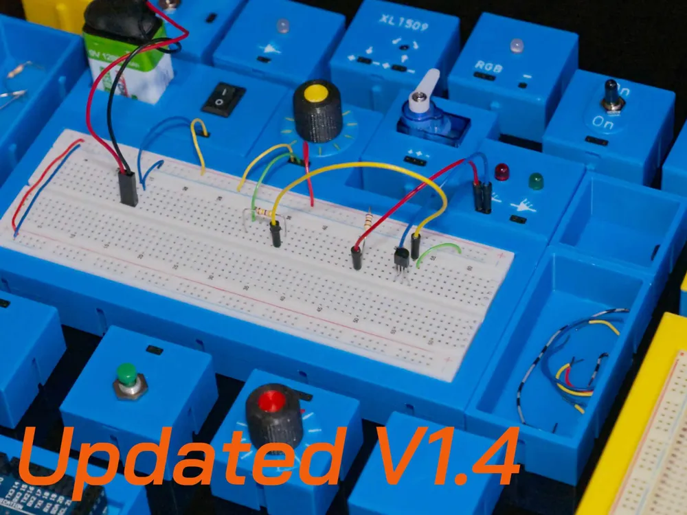
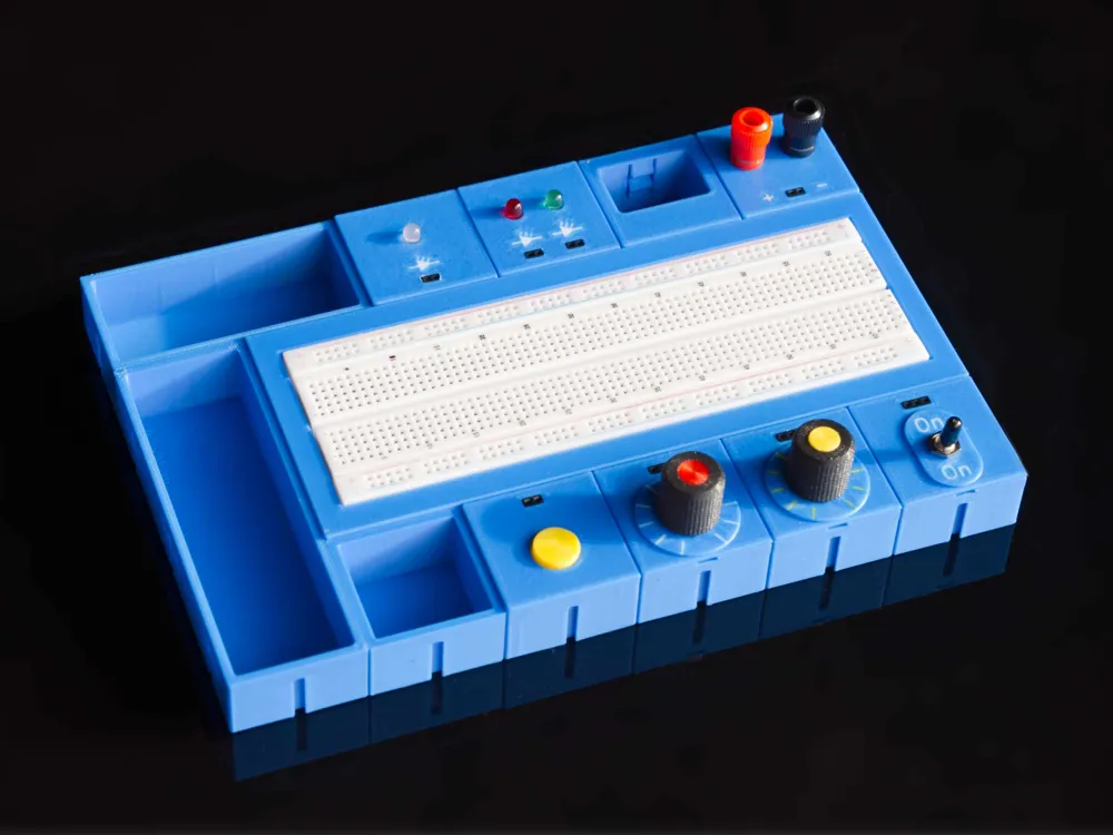
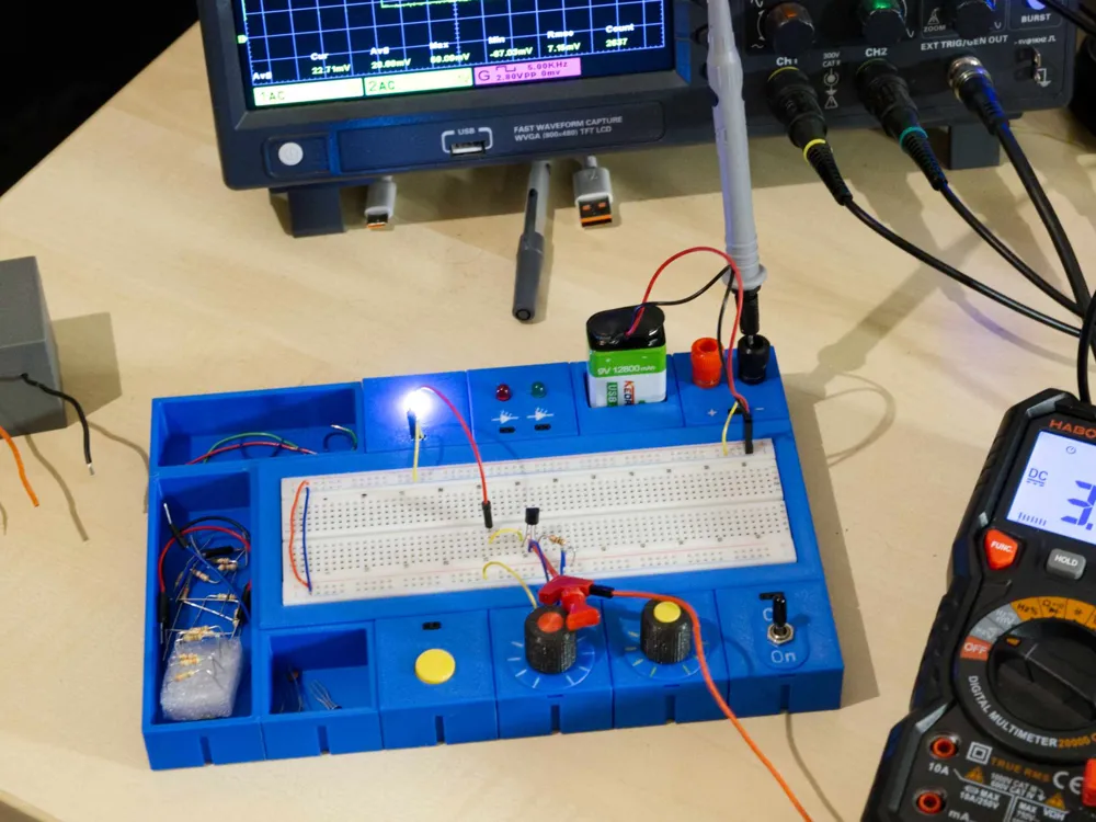
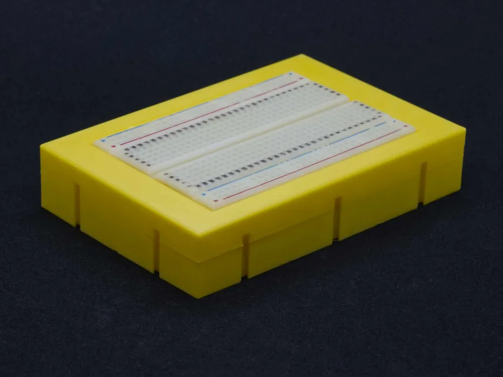
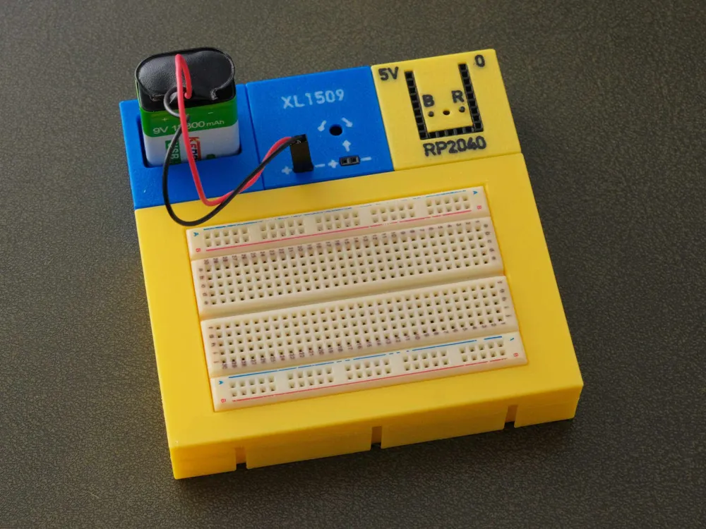
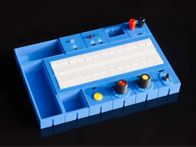
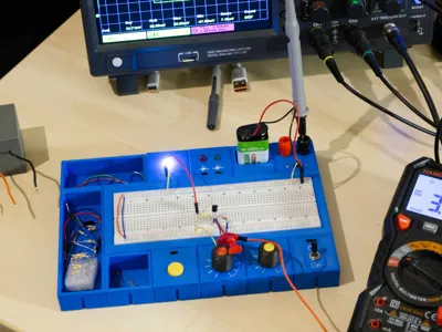
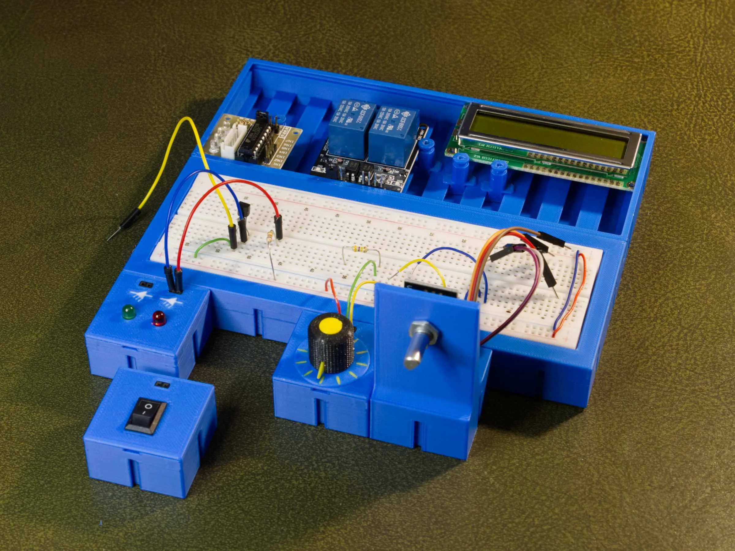
Building Block Trainer Board
Whether for electronics crafting, self-study, training courses, or in school, this is a universal system for building individual boards
The Idea
After I stumbled upon the YouTube video channel Attractor, which is highly recommended by the way, I had the idea to make breadboard setups a bit more professional and stable. After numerous concept ideas and failed attempts, this system finally emerged months later
Yes, I invested a lot of time and filament to bring it into its current form
The Principle
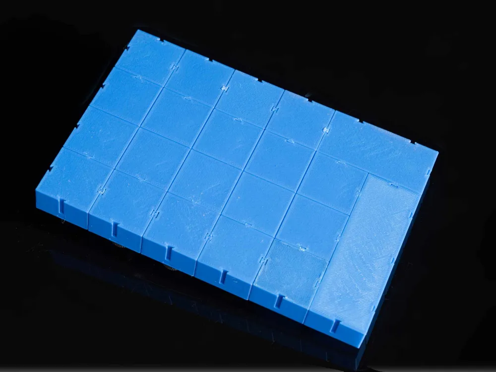
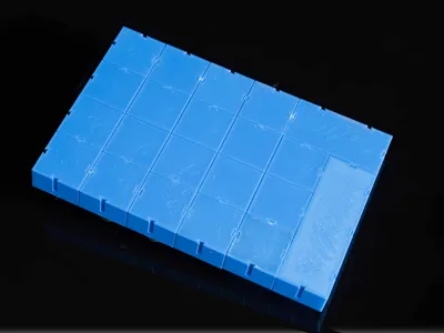
The modules are built on a 36x36 mm grid, which in my opinion is the best compromise between compactness and easy assembly
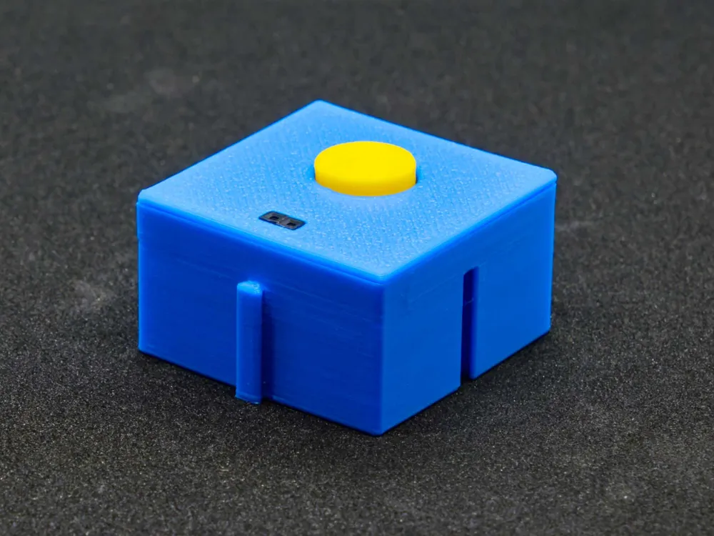
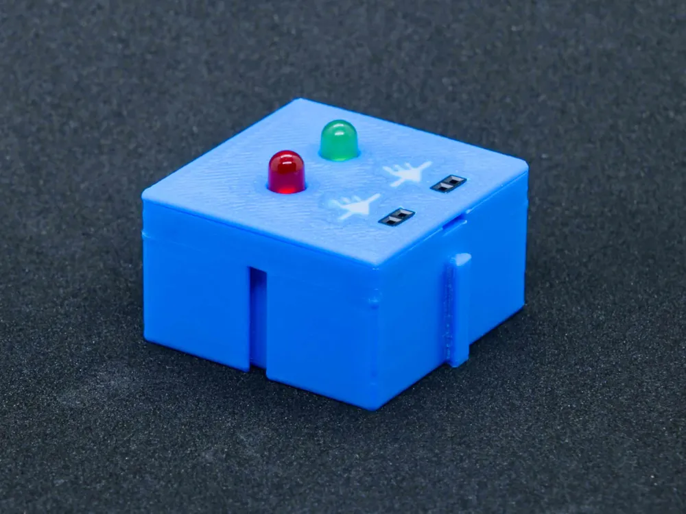
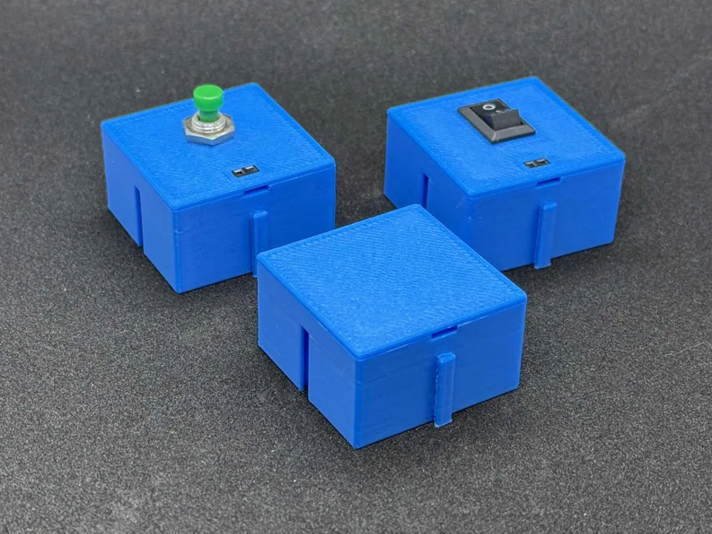
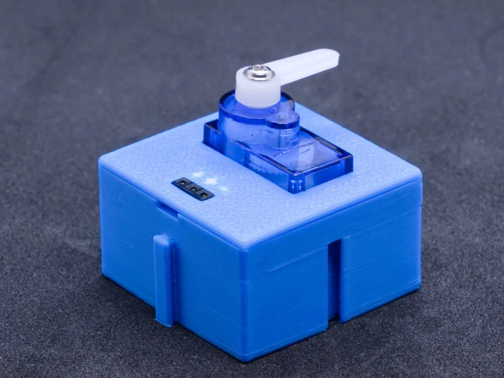
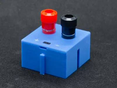
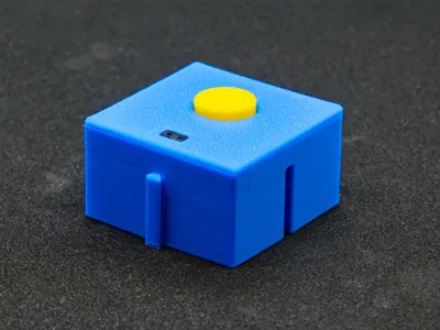
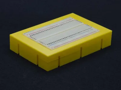
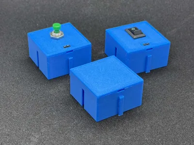
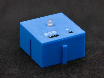
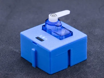
Most modules are housed in a carrier box (BB-25-02-xx). The entire electronics are attached to the insert
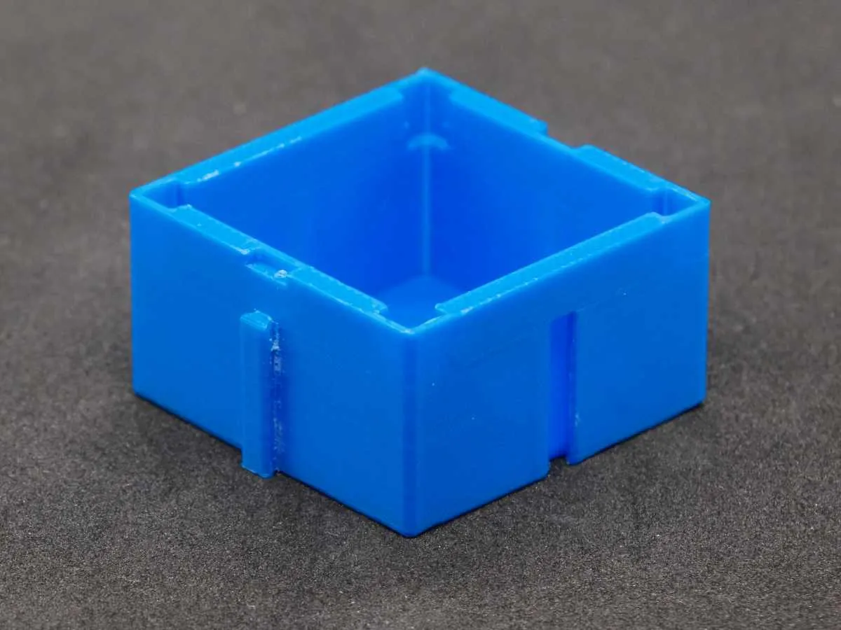 | 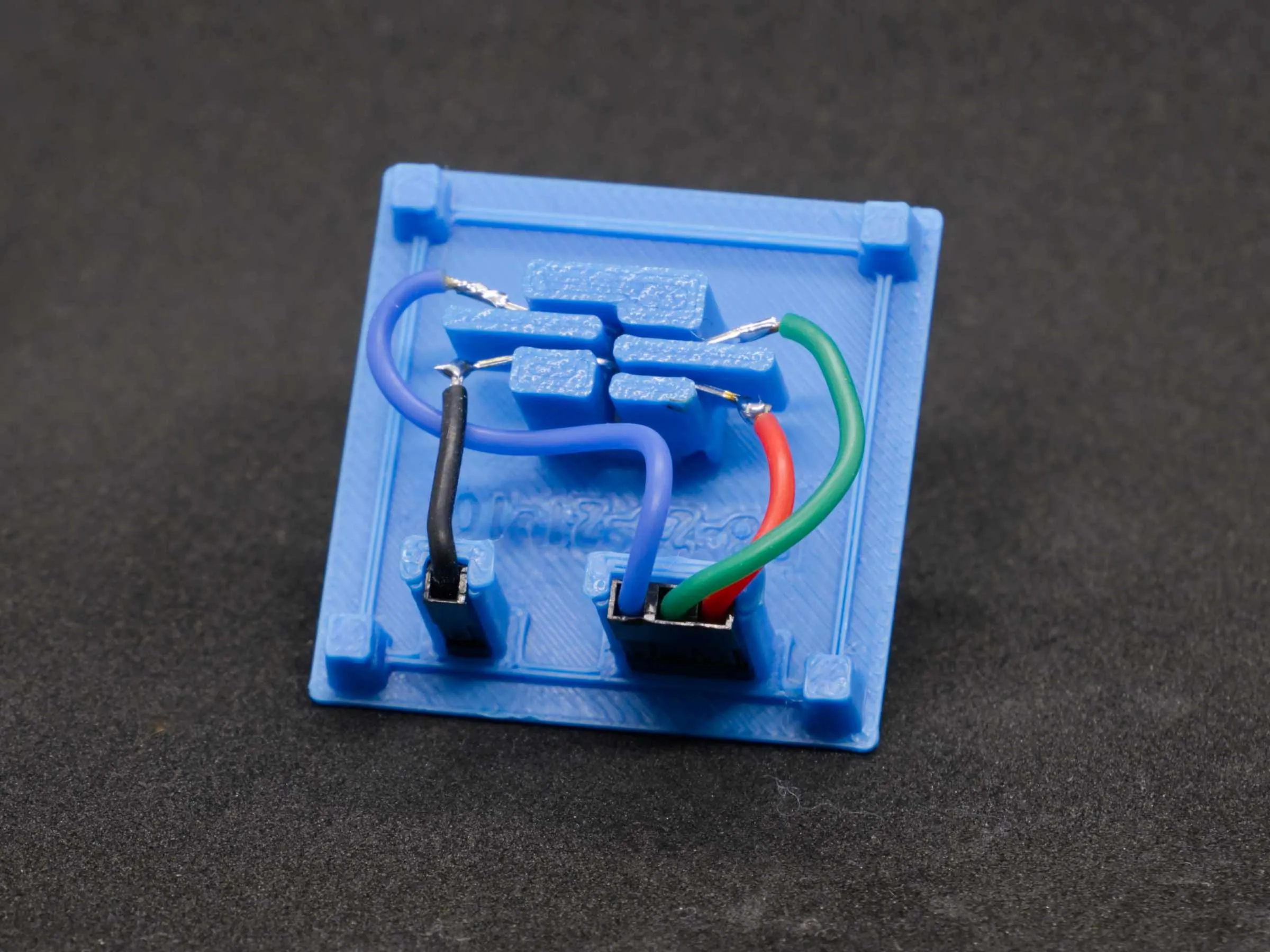 |
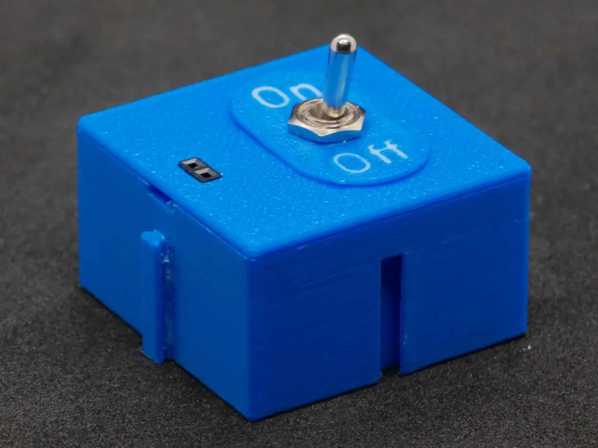
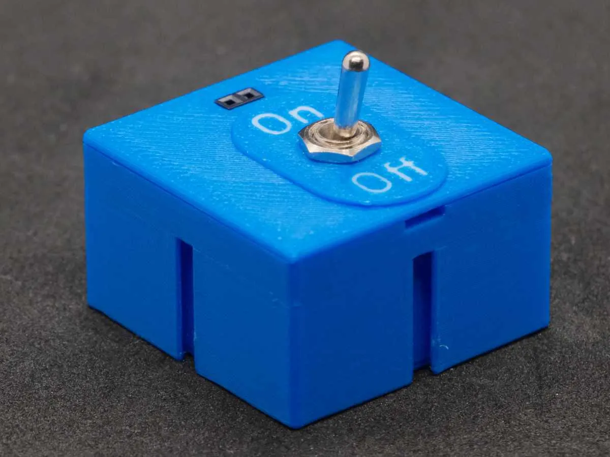
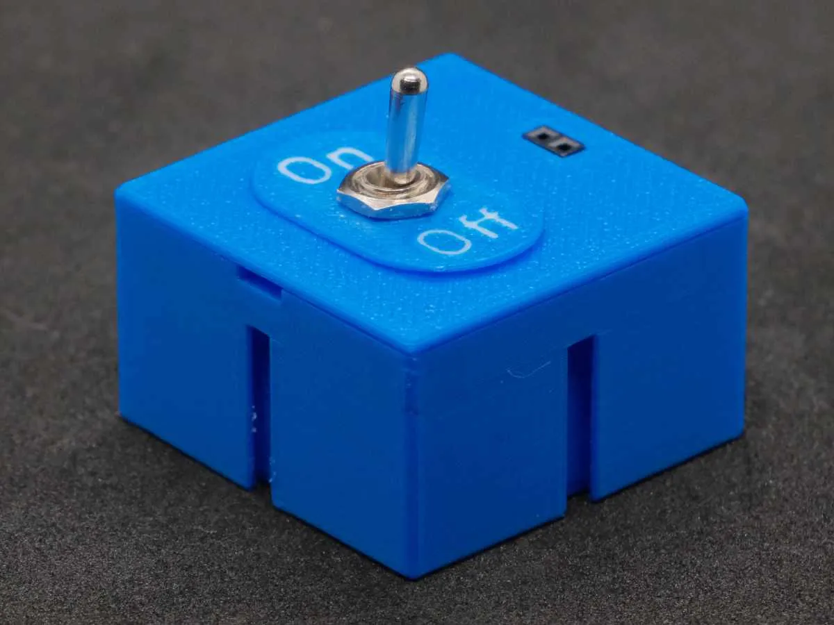
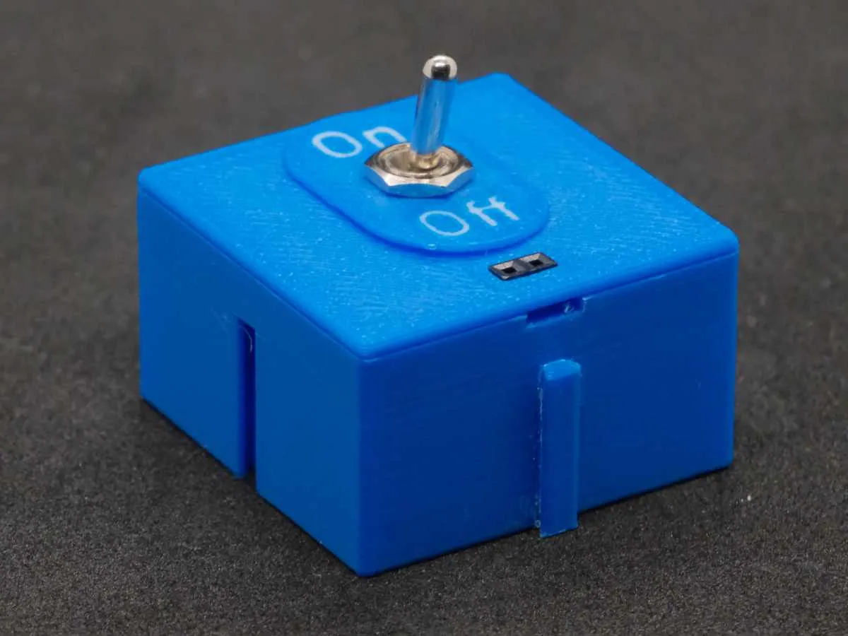
This not only allows for easier assembly but also for the inserts to be rotated as desired. This means you can attach the box to any side of another box and still rotate the insert to ensure optimal usability
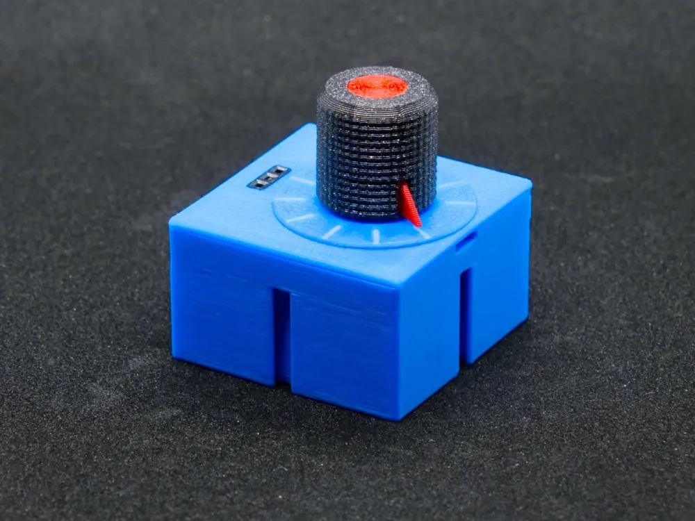
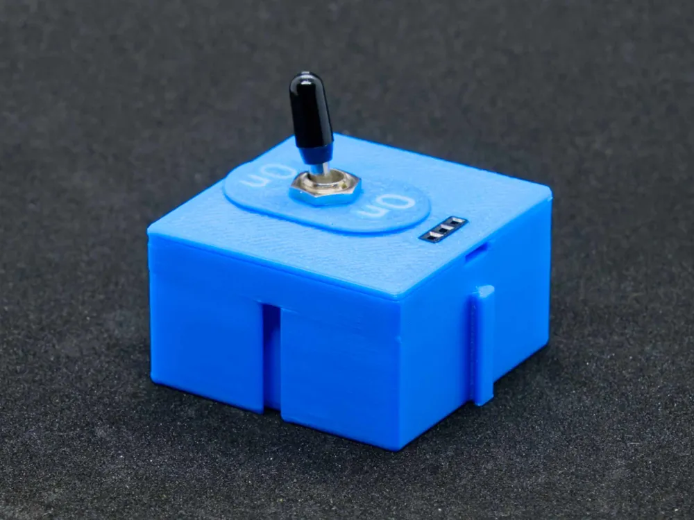
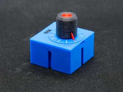
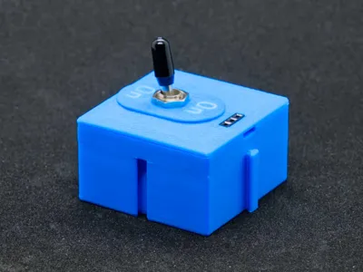
For operating elements, such as switches and potentiometers, the labeling and the element can also be freely rotated in 90° steps
 |  |  |  |
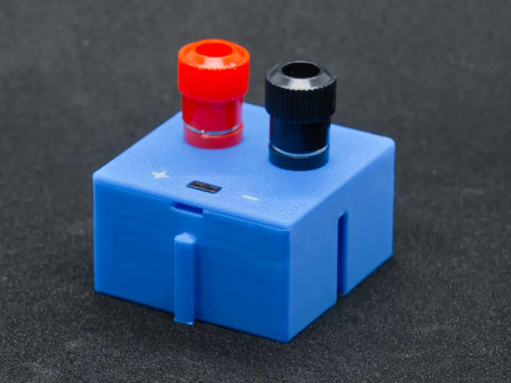
All modules have been optimized with wiring in mind, so that with careful assembly, short circuits are virtually impossible even after prolonged use. For this reason, Dupont sockets are also used as connections. These also offer the advantage that the wiring on the board corresponds to that of the modules, meaning no special cables are needed
The modules are divided into the following groups:
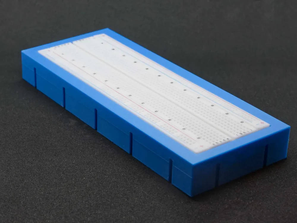
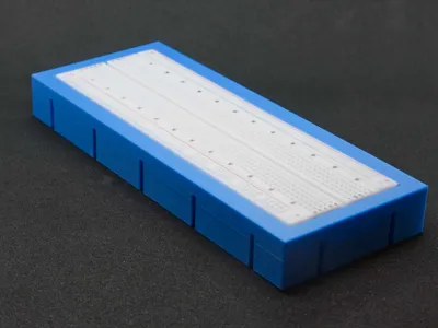
- Breadboard
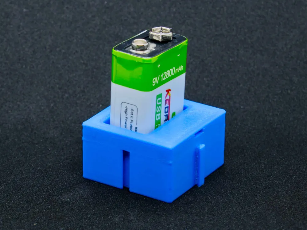
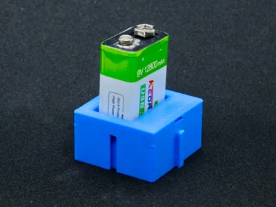
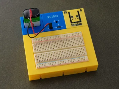
- Power Supply
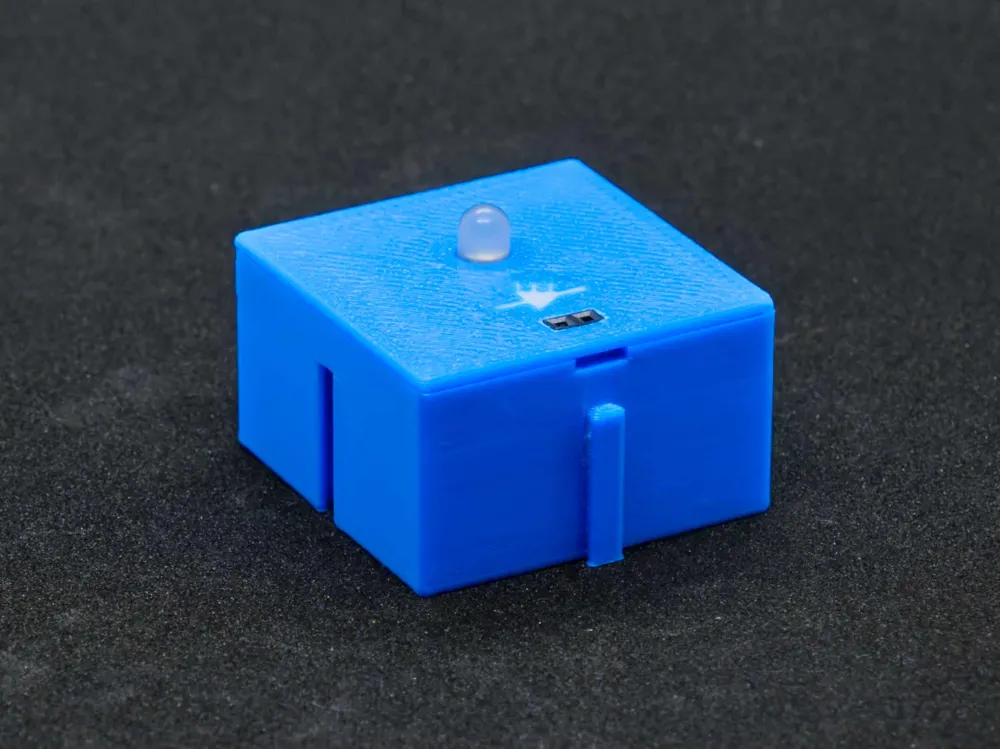
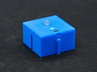
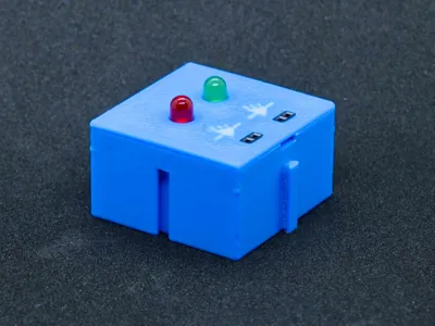
- Output elements such as LED
- Control elements such as buttons, potentiometers and switches
- Microcontrollers (as a separate MakerWorld project)
All power supply modules and all output modules are designed for mounting above the breadboard and always have the positive connection on the left and the negative on the right. Similarly, the input is on the left and the output is on the right if there are inputs and outputs
A Personal Note
This model is freely provided by me here to open up new possibilities, especially in the field of education where money is always tight. As stated, you can download this model here for free, but you must adhere to the rules
The Rules
- It is not permitted to sell the model files or parts printed with them, or to market them otherwise for profit!
- It is not permitted to pass on or publish the model files or documentation! Always share the link to this page. This is the only way improvements can reach users
- It is permitted to make as many prints as you need, especially for your students!
- It is permitted to publish pictures of your prints with a link to this page
- If you provide feedback, which I would greatly appreciate, but do not give 5 stars, please write what you don't like or what you would improve. 4 or fewer stars without comment are disrespectful; they benefit neither me nor others. With an appropriate comment, 1 star is, of course, also okay :-)
The Print
The easiest way is to use the attached print profile. Unneeded parts can be hidden under “Objects” in Bambu Studio by unchecking the green box
This model contains a number of small details and precise fits, therefore, it is necessary to calibrate the filament properly and clean the build plate well beforehand with soap, warm water, and a brush. A new textured plate can be thoroughly scrubbed with steel wool (e.g., one with integrated soap) to achieve significantly better adhesion
I had already published the knob for the potentiometer
Now also blocks for RP2040 and ESP32-C3 available!
Colors
Of course, other colors also look good! This can be changed quickly by simply changing the color on the respective filament. If you want to color individual parts differently, this is also easily possible
- Select the part by clicking on it with the mouse (e.g., the LED holder for two LEDs)
- Rotate the board so you see the underside
- Zoom in until you see the marking clearly
- Click the paint bucket
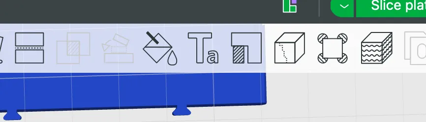
Select paint bucket and edge detection
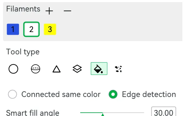
Now you can hover over the symbols or text and color them with the selected color
Parts
Here are some AliExpress links for the parts I used. No guarantee that these are the cheapest offers, but I was satisfied with the quality
- Breadboard
- Rectangular switch
- Toggle switch On/On (can, of course, also be used for On/Off)
- Potentiometer, depending on the application, I recommend 100kΩ or 10kΩ
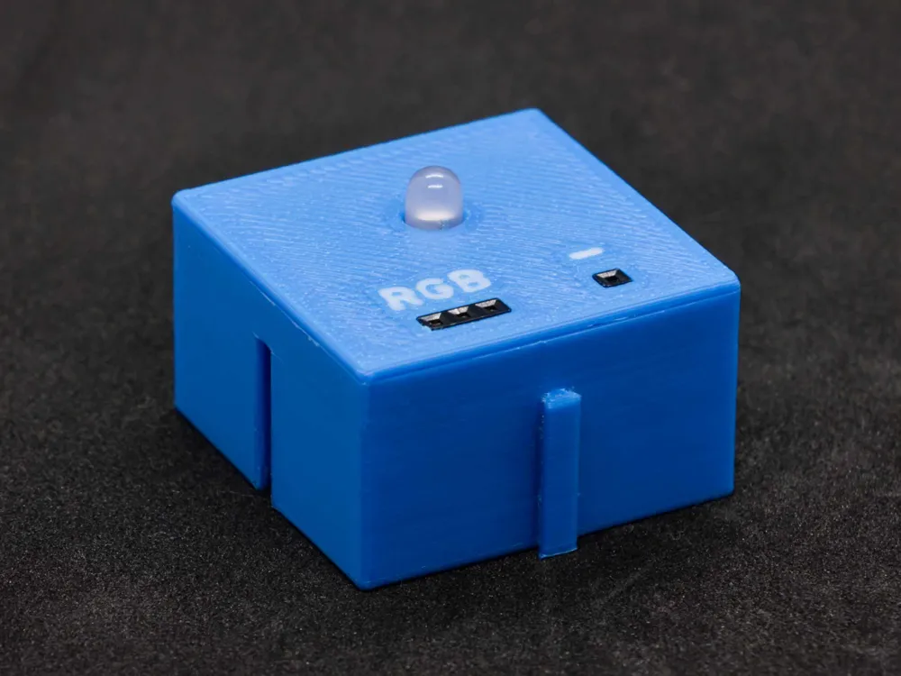
- RGB LED Common Cathode
- Dupont cables, female-female
- XL1509 Step-Down converter with adjustable output voltage
I receive a small commission if purchases are made through these links
Assembly
The assembly of the individual functional blocks is hopefully explained with sufficient detail by pictures in the attached assembly instructions
Wiring
For wiring, I recommend ready-made “female-female” Dupont cables. These are cheaply available everywhere and save you the not-so-simple crimping process
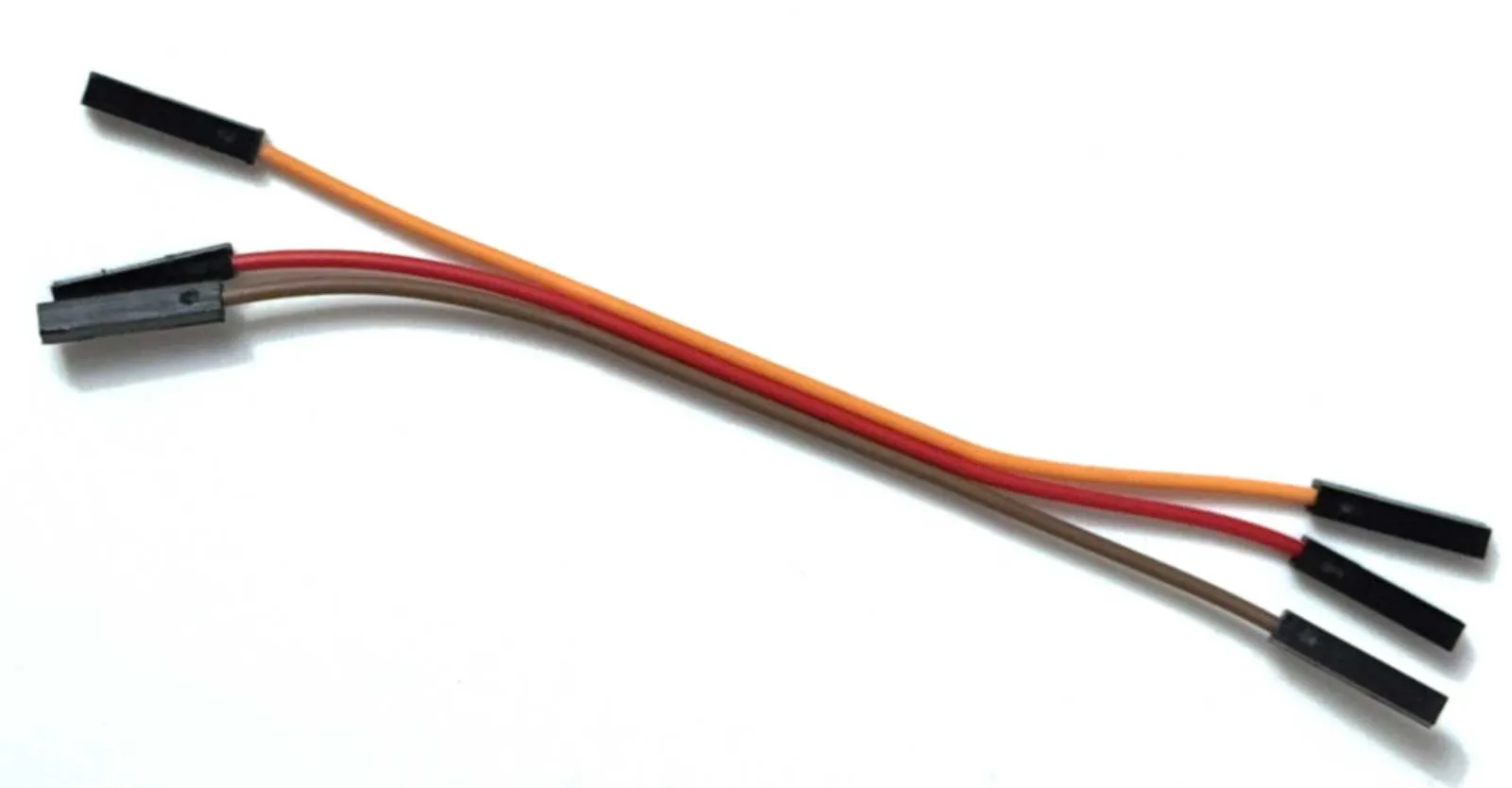
These cables can simply be cut in the middle, and you'll have pre-assembled cables for one or two boxes
For the power supply connection, I recommend soldering a 100µF electrolytic capacitor and a 100nF ceramic capacitor in parallel with the connections inside the box. This prevents interference voltages, especially with longer supply lines
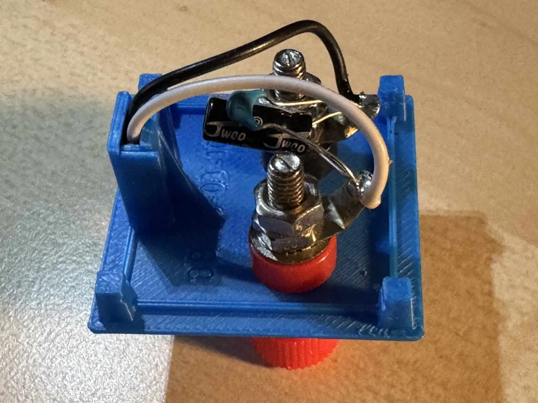
Costs for a Trainer Board
In my experience, a board like the one shown can be created with less than 10 Euros in material costs. The parts are available from common electronics retailers or on AliExpress. Anyone who already owns an electronics kit likely already has most of the parts and also the cables
Tips
- Don't use the cheapest breadboard; they usually have very poor contact springs
- For wiring, use tinned wire with approximately 0.6 mm diameter. Copper wire quickly forms a corrosion layer, which makes your circuit unreliable. I found 3 cm, 5 cm, and 7 cm lengths to be quite universal
- Dupont cables have a square contact, which can wear out the contact springs in the breadboard if not inserted carefully (straight)
Final Words
I wish you much joy with your individual trainer board and would appreciate feedback, preferably with a picture. Of course, I would also be happy about a like or boost!
Updates
17.11.25 A module for rectangular switches, a module for round buttons, and an empty module as a spacer
20.11.25 New module for a half breadboard, updated assembly instructions, base with a small update to version 1.1
22.11.25 XL1509 Step-Down Module
24.11.25 RGB-LED module for common anode and common cathode, minor updates to the LED modules. Updated assembly instructions
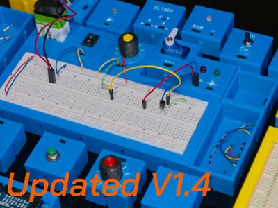
04.12.25 Servo SG90 module added, assembly instructions updated to version 1.4, minimal improvements to various modules
28.04.26 Base and half base modified to reduce the formation of a “waterline”. Print profile updated
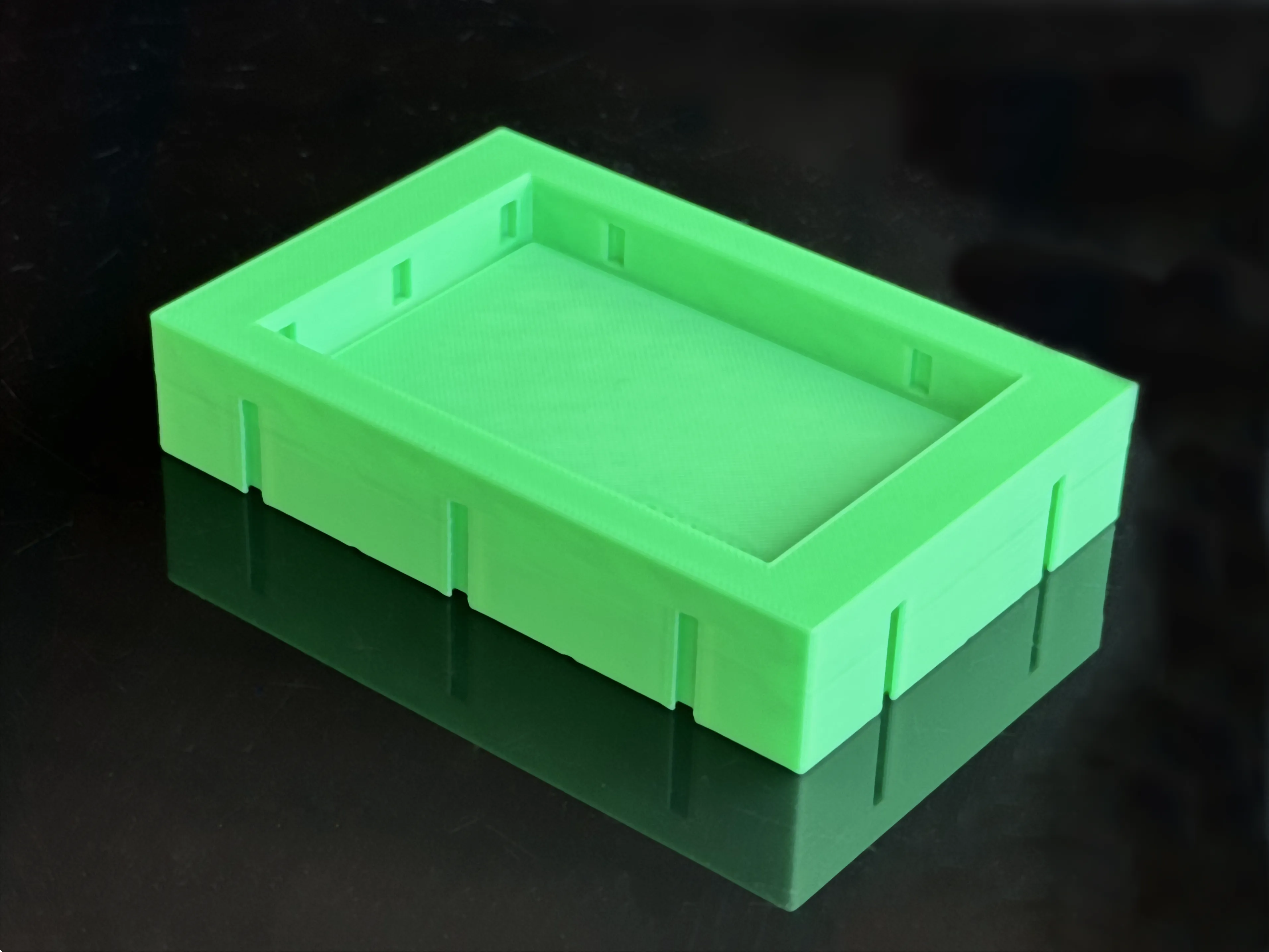
18.06.26 Significantly improved connectors on all boxes. New, optimized print profile
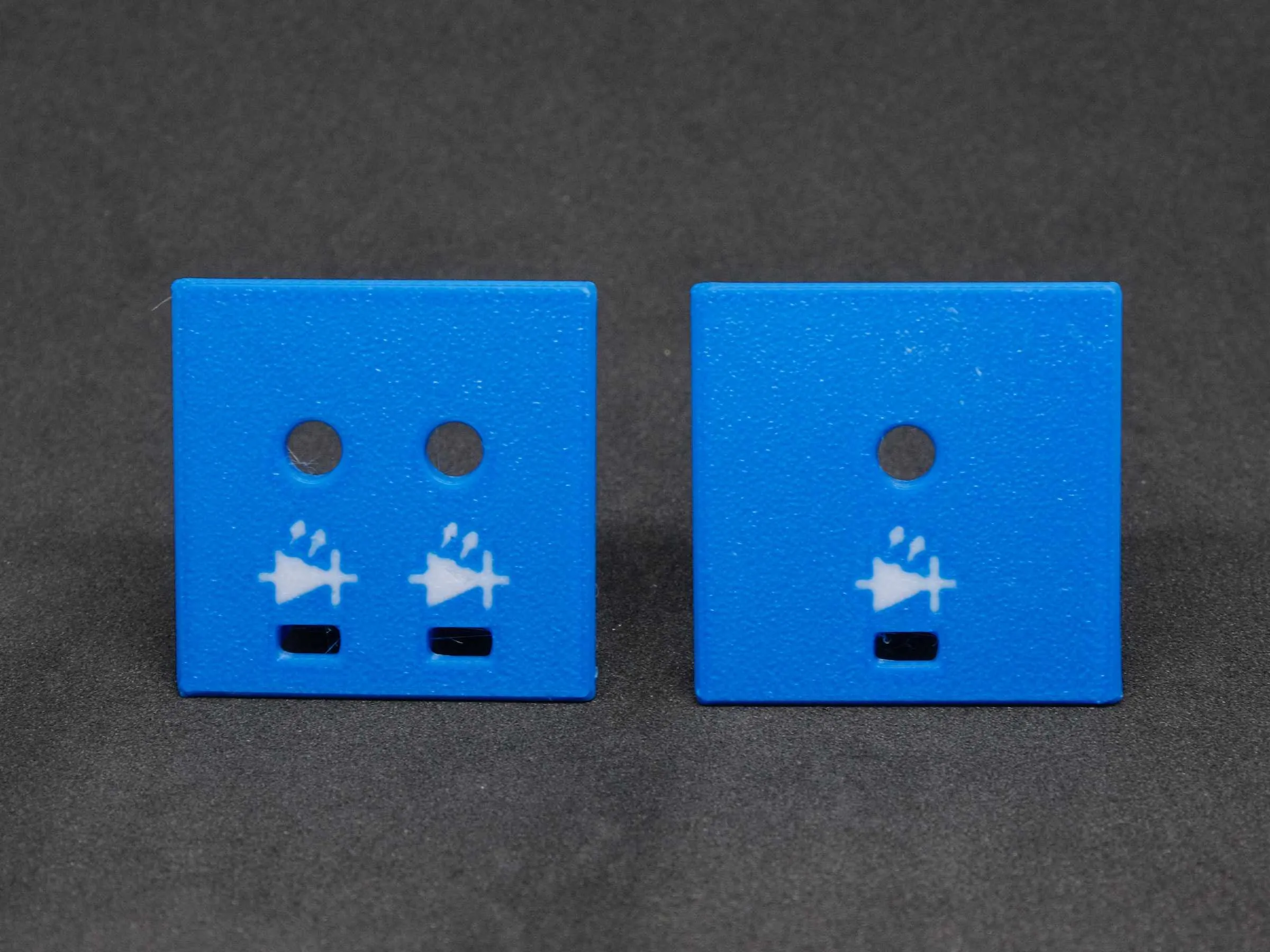
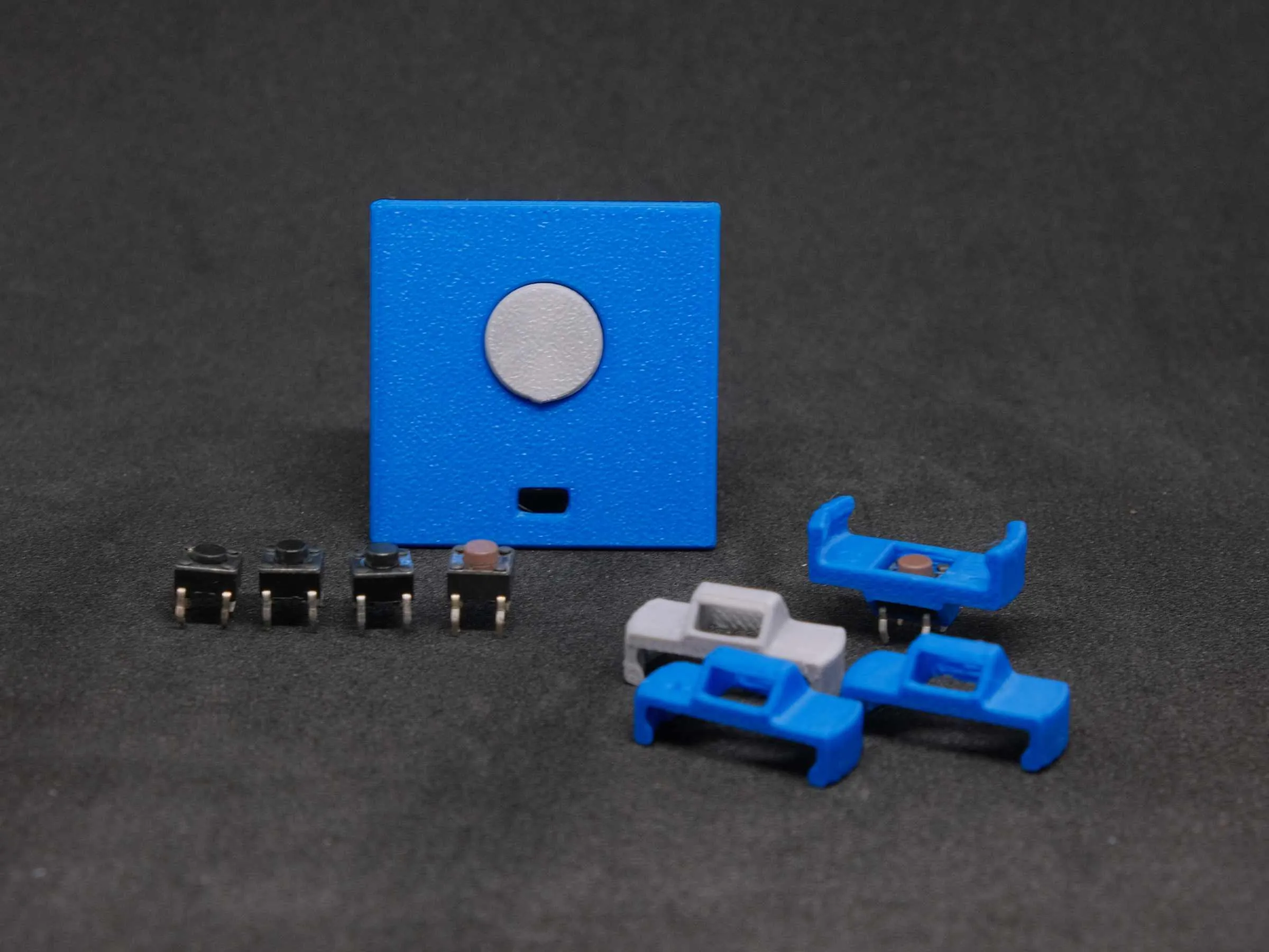
13.07.26 New LED symbols and holders for 6x6mm buttons with 4.3mm, 4.5mm, and 5mm height added
 |  |
15.07.26 New print profile with correction of the base for a full breadboard. Additional change of covers to inner/outer print order
All B3S models can be found in the B3S Collection
If you like this model, you might also like other models from me, e.g.:
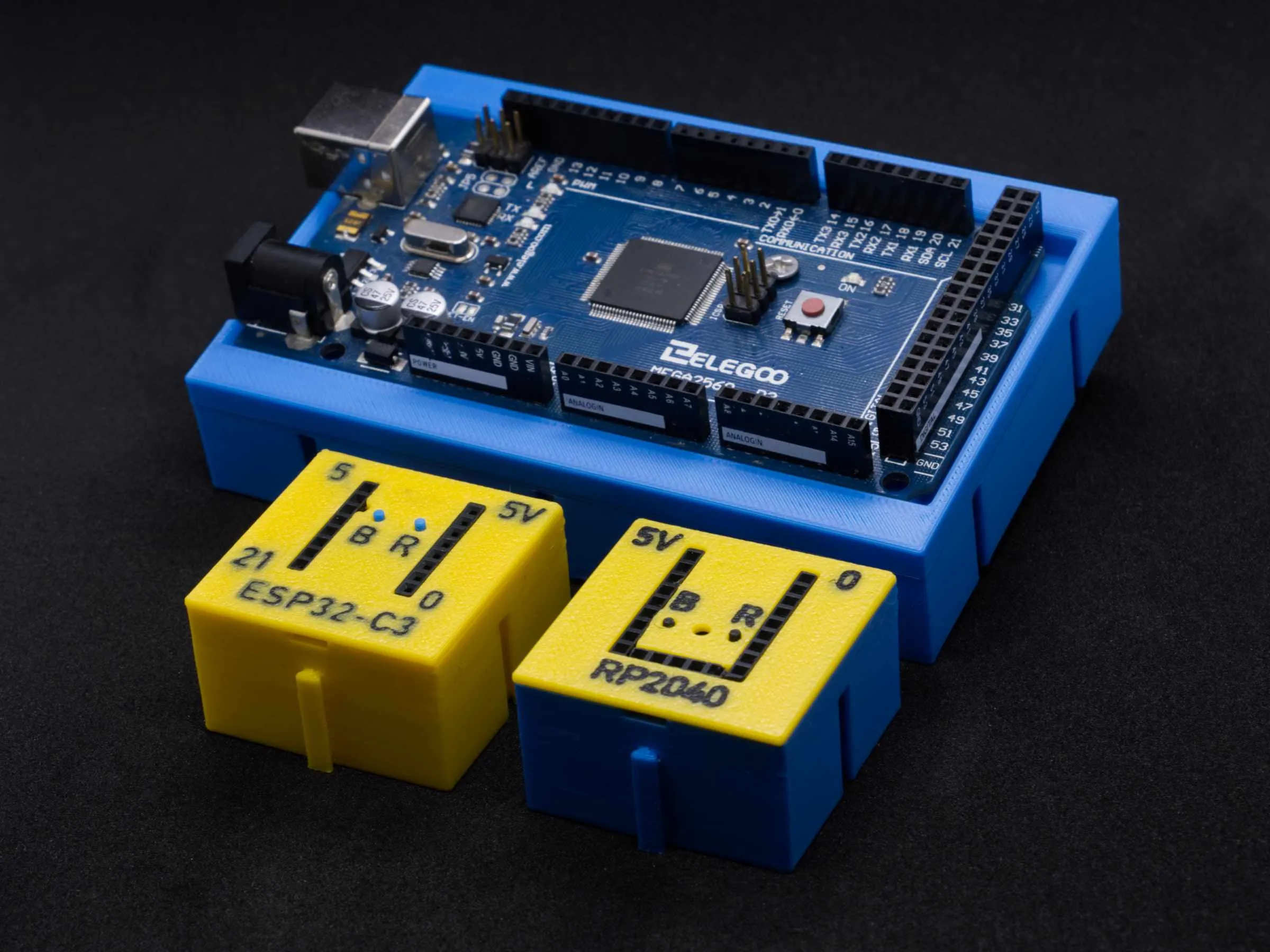 |  | 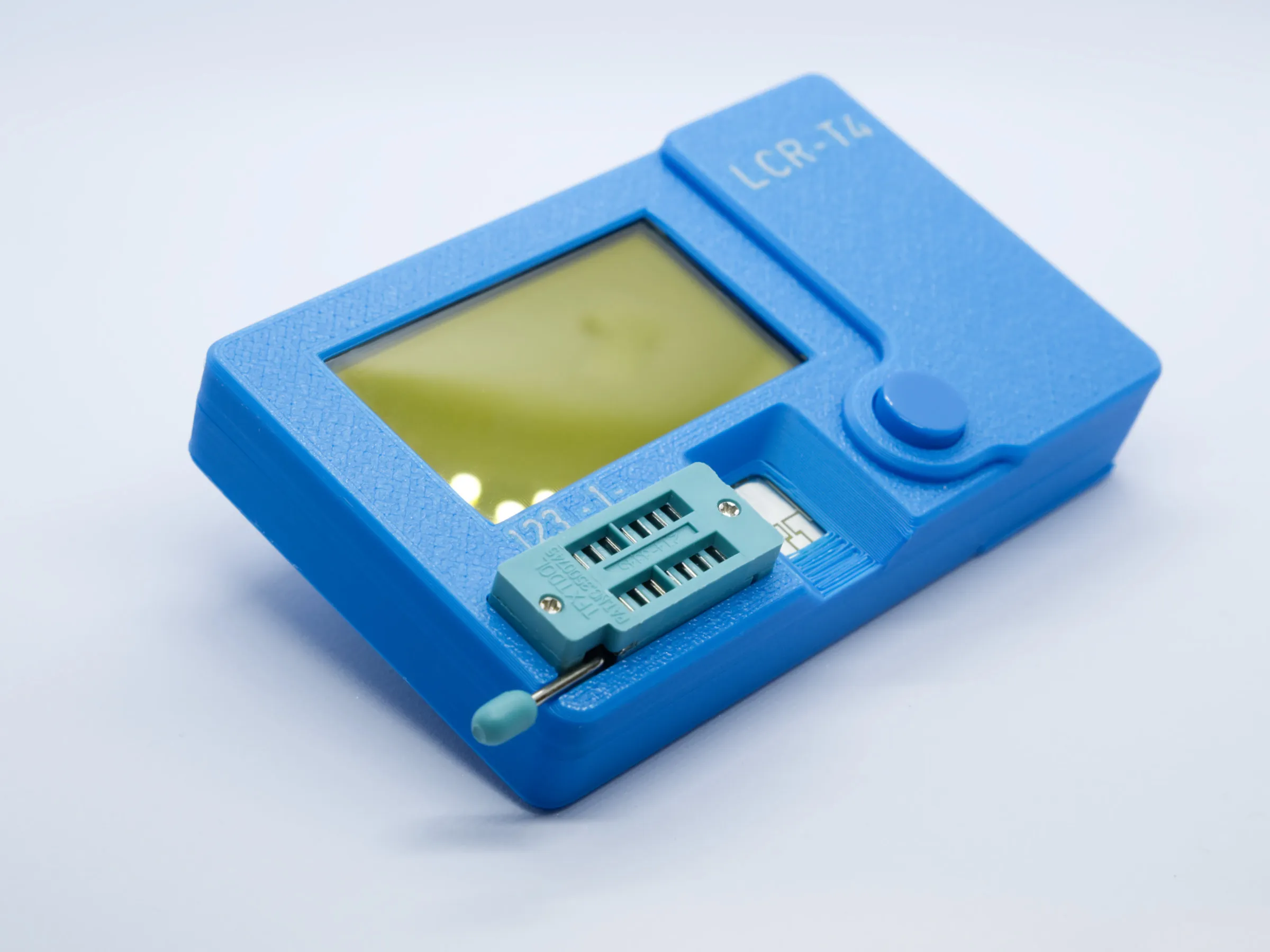 | 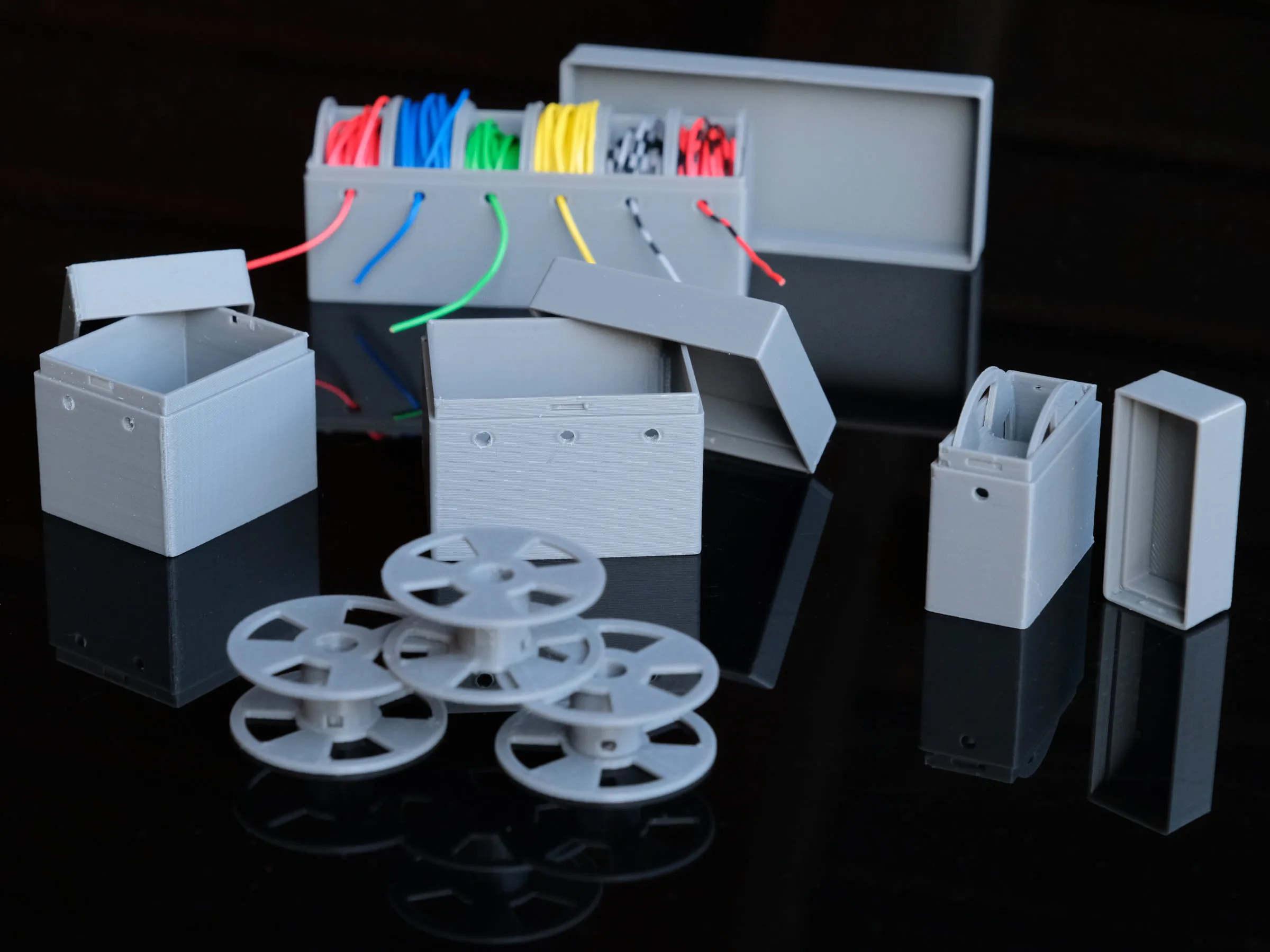 | 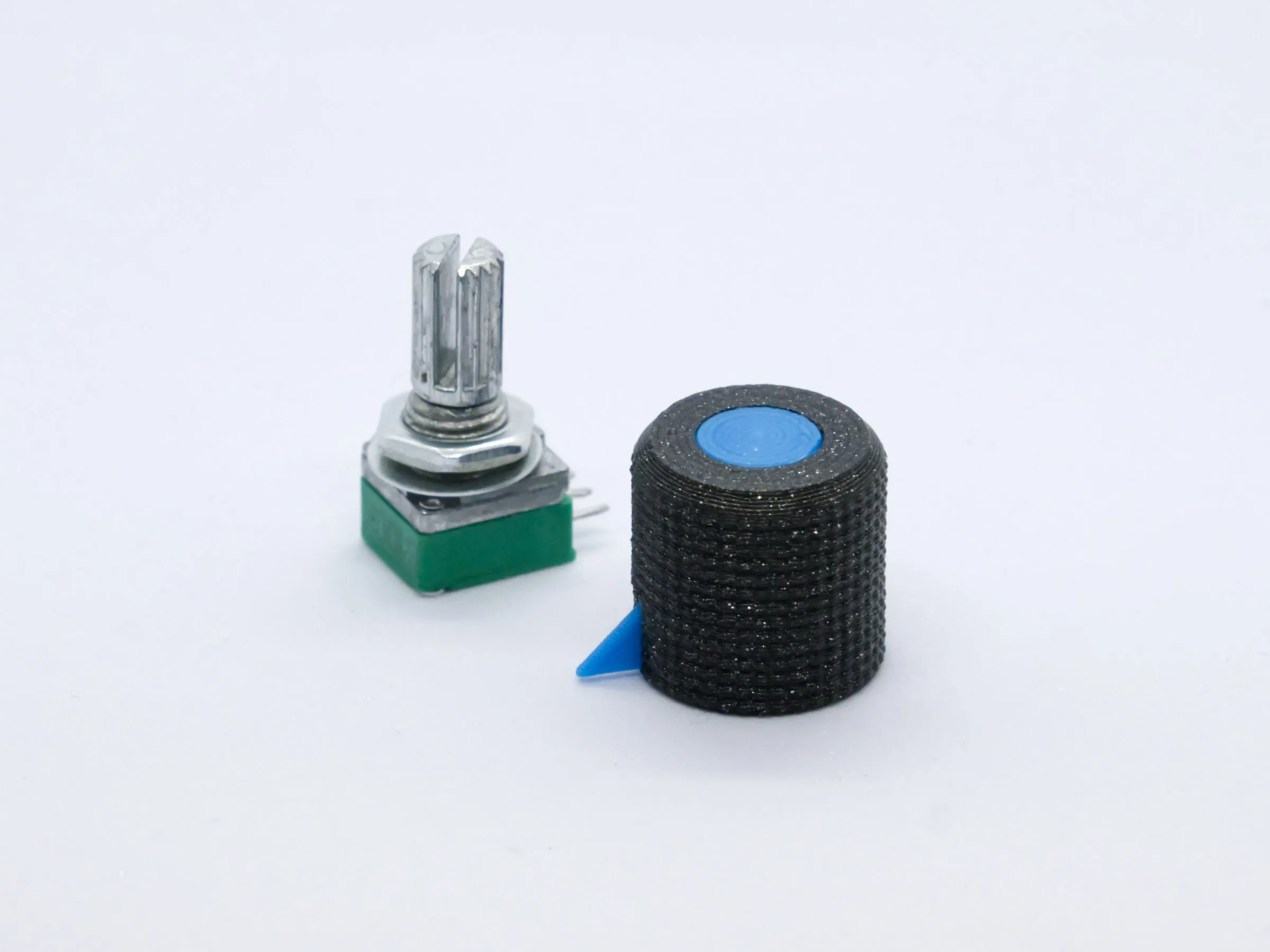 |
| Microcontroller blocks | Breakout board holder | LCR-T4 Case | Wire Holder (different variants) | Potentiometer Knob |
Documentation (1)
License

You shall not share, sub-license, sell, rent, host, transfer, or distribute in any way the digital or 3D printed versions of this object, nor any other derivative work of this object in its digital or physical format (including - but not limited to - remixes of this object, and hosting on other digital platforms). The objects may not be used without permission in any way whatsoever in which you charge money, or collect fees.


Comment & Rating (26)