NFC Access Controller - Home Assistant


Print Profile(1)

Description
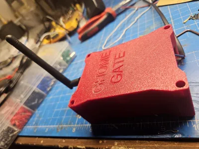
🔴 GHome Gate – NFC Access Controller for Home Assistant
A compact, fully-integrated NFC access controller designed for Home Assistant, powered by ESPHome, and packaged inside a custom 3D-printed enclosure.
This device allows you to trigger Home Assistant automations simply by tapping an NFC tag on the external reader.
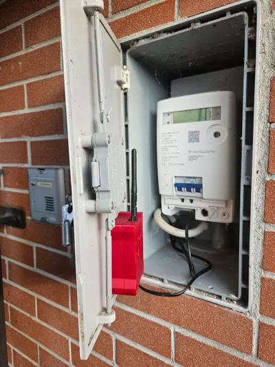
It is built to be installed inside the utility meter cabinet and powered directly from 230 VAC, making it a fully autonomous access module for gates, doors, alarms, and automations.
⭐ Features
- ✔️ PN532 NFC reader (I2C)
- ✔️ ESP8266 NodeMCU running ESPHome
- ✔️ Direct 230 VAC → 5 VDC power via Hi-Link isolated PSU
- ✔️ External NFC antenna + internal buzzer feedback
- ✔️ Designed for outdoor electrical cabinet installation
- ✔️ Instantly sends tag ID to Home Assistant (tag_scanned)
- ✔️ Custom beeps, LED status, OTA updates, API encryption
- ✔️ Fully open-source and customizable
📦 Bill of Materials (BOM)
Electronics
| Component | Qty | Notes |
|---|---|---|
| NodeMCU v2 ESP8266 | 1 | Main microcontroller running ESPHome |
| PN532 RFID/NFC Module (I2C version) | 1 | Mounted inside the external reader shell |
| Hi-Link HLK-PM01 (100–240VAC → 5VDC) | 1 | Compact isolated power supply |
| Passive buzzer (5V) | 1 | Connected via PWM (GPIO12) |
| Prototype board (70×50 mm) | 1 | For ESP + PSU mounting |
| External WiFi antenna | 1 | Required due to metal cabinet shielding |
| Header pins + jumper wires | various | Internal wiring |
| M3 brass threaded inserts | 4 | For robust enclosure assembly |
| M3 screws | 4 | Cover fastening |
3D Printed Parts
| Part | Material | Notes |
|---|---|---|
| Main enclosure (GHome Gate) | PETG / ASA | Heat-resistant, durable |
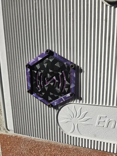
| Front cover with embossed logo | PETG / ASA | |
| External NFC reader mount | PETG / ASA | Adhesive mounting |
| Internal panel spacers | PETG |
Other
- Heat-shrink tubing
- Cable ties
- Silicone or double-sided pads
- 230 VAC double-insulated cable
⚙️ Hardware Overview
The device is composed of two physical modules:
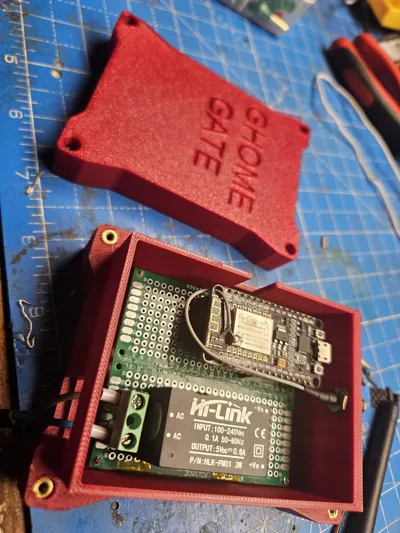
1. Main Controller Box
Contains:
- NodeMCU ESP8266
- Hi-Link power module
- Buzzer
- I2C connection to NFC reader
- WiFi antenna connector
This box is installed inside the meter cabinet, powered directly by 230 VAC.
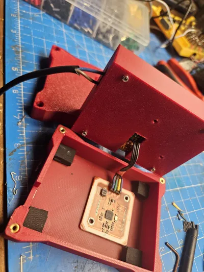
2. External NFC Pad
Mounted outside the cabinet door.
This contains the PN532 board, placed close to the plastic surface for maximum tag detection reliability.
The two modules are connected internally through a small ribbon cable (SDA, SCL, 5V, GND).
🔌 Pinout / Wiring
NodeMCU → PN532
| PN532 | NodeMCU |
|---|---|
| SDA | GPIO4 (D2) |
| SCL | GPIO5 (D1) |
| VCC | 5V |
| GND | GND |
NodeMCU → Buzzer
| Buzzer | NodeMCU |
|---|---|
| Signal | GPIO12 (D6) |
| VCC | 5V |
| GND | GND |
Power Input
| Hi-Link Output | NodeMCU |
|---|---|
| +5V | Vin |
| GND | GND |
🧠 ESPHome Configuration
Below is the firmware used in this project (ready to copy/paste):
https://github.com/RazorCopter/home-assistant/blob/dev/Stack_esphome
🏡 Home Assistant Integration
This module integrates natively with Home Assistant through ESPHome API.
When a tag is scanned:
Home Assistant receives:
tag_scanned: id: <tag_uid>
You can use this to trigger:
- gate control
- door unlocking
- alarm arming/disarming
- presence detection
- custom automations
Audio feedback
You may call:
- button.beeep
- button.test_doppio_beep
Or trigger the services exposed by API:
- esphome.gate_beep
- esphome.test_doppio_beep
🖨️ 3D Printing Instructions
Recommended settings:
- Material: PETG or ASA (heat & outdoor resistant)
- Layer height: 0.2 mm
- Perimeters: 3
- Infill: 20–30%
- Supports: No (all parts designed with self-supporting geometry)
- Bed temp: 75–80°C
- Hotend: 235–245°C
Notes:
- Brass inserts should be heat-pressed into the main body.
- External NFC cover should not be thicker than 2.0–2.5 mm for best read performance.
- Antenna connector hole supports SMA bulkhead connectors.
🔧 Assembly Instructions
- Solder the NodeMCU and Hi-Link to the prototype board
- Wire SDA/SCL/5V/GND from NodeMCU to PN532
- Mount the PN532 into the external reader shell
- Install brass inserts into the 3D-printed case
- Route the I2C cable between the two shells
- Connect buzzer to GPIO12
- Close the main enclosure using M3 screws
- Mount the external pad on the door using screws or adhesive
- Install the main module inside the electric meter cabinet
- Upload ESPHome firmware via USB or OTA
- Add the device to Home Assistant
🧩 How It Works
- When an NFC tag approaches the external pad,
- The PN532 recognises the UID
- ESPHome immediately sends it to Home Assistant
- Home Assistant triggers the configured automation
- The buzzer provides audio feedback
- The status LED shows connectivity and OTA updates
A complete, local, private access system with instant response.
🛡️ Safety Notes
⚠️ The Hi-Link module handles 230 VAC.
Installation must be done with the power disconnected, and ideally by someone experienced.
⚠️ Always use a double-insulated 230 V cable.
⚠️ Do not expose the main enclosure to weather (keep inside the cabinet).
📜 License
This project is released under the MIT License.
You may reuse, modify, or republish the files as long as credit is provided.
Comment & Rating (0)