Search models, users, collections, and posts
Steel Turret Directional Clamping Manual Vise - Model Woodworking Painting Modification (Directional Angle Retention, 360-Degree Rotation, Automatic Limit)
IP Report


GIF
Print Profile(2)
Steel Turret Manual Bench Vise (Mini-compatible)
Designer
13.5 h
5 plates

Clamping column TPU sleeve and base anti-slip pad
Designer
1.8 h
2 plates
Open in Bambu Studio
Boost
35
64
0
1
13
4
Released
Description
Content has been automatically translated.
Boost Me (for free)
If you encounter any problems, you can send me a private message. I will reply within 24 hours. Please do not leave a bad review if you encounter problems, much love~
Other Steel Mecha Style Practical Models (Click image to jump)


Model Introduction:
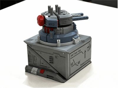
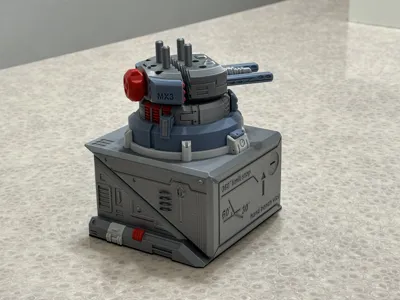
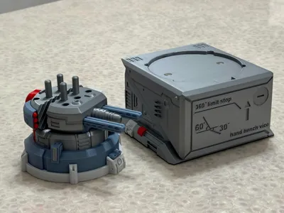
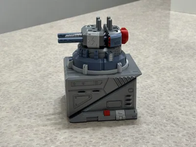
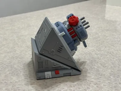
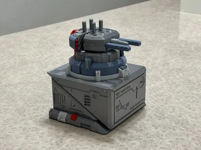
I wanted to make my entire computer desk look cool. To match my mecha footrest and mecha phone holder, I made this steel turret-shaped desktop vise. It has powerful clamping functions, suitable for painting, modifying, and sanding models and woodworking projects. It provides stable clamping support and maintains a set angle. Plus, even when not in use, it looks incredibly cool on your workbench! It has the following features (See video below for functional demonstration):
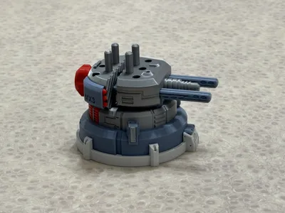
The turret vise can rotate 360 degrees with self-limiting stops, allowing it to stay and hold at any angle. The turret alone can be used as a handheld desktop vise
Comes with clamping posts, which can clamp curved and irregularly shaped parts. The clamping posts can be adjusted in position according to the part
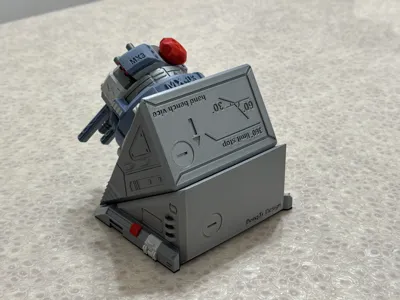
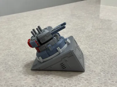
The base allows for adjustable combination angles, providing support surfaces at: horizontal, 30 degrees, and 60 degrees. The combination of the turret and base can offer you more suitable working angles
The base has filling holes. It is recommended to fill it with rice or sand and cover it with screw caps. After filling, it provides significant counterweight for reliable stability for your handicraft
The clamping posts are equipped with TPU sleeves, which provide more reliable clamping ability. (Recommended for those with TPU filament)
The base is equipped with TPU anti-slip pads, which provide more reliable anti-slip stability. (Recommended for those with TPU filament)
You can use rice or sand to add weight

TPU accessories can be installed for better stability

Installation Instructions (Assembly diagrams are in the attachment):
Model installation requires glue, a flat-head screwdriver, and magnets (default specification is 8X2MM. It is recommended to use official magnets. Please do not use inferior magnets as their size and magnetic force may not meet standards)
Magnets are recommended for installation. It can still be used without them, but the overall texture and reliability of the combined effect will decrease. Magnet specifications can be adjusted in the slicer software, the method is described later
The model has moving parts. Do not print the turret body using low-strength filament, such as PLA Matte and Lite filament. The author used official PLA Basic filament: silver, blue-gray, light gray, and red
Functional Usage Demonstration
How to modify the magnet mounting holes to your required specifications (greater than 8MM). A tutorial is provided below:
First, open this model's 3MF file with the Bambu Studio slicer software on your computer. Create a new negative part on the plate and adjust it to your desired magnet size, for example, 10.1X3MM (a tolerance of 0.1 to 0.2 needs to be reserved)
Second, select both the newly created negative part and the model body simultaneously. Then you can click the assembly function button. Selecting only the negative part will not work
Third, in the assembly function, select Face 1 (fixed) as the bottom surface of the model's original hole, and Face 2 (movable) as the top surface of the negative part. Click to center and align, and the negative part will then be in the opening position
Fourth, the original hole depth is 2MM. If the negative part height is 3MM, use the move function to move it down by 1MM, so the hole depth becomes 3MM
Fifth, slice and print. You will then see the hole in the slice preview change to your desired size
Vise
Clamping
Handcraft
Desktop
Tools
Livery
Model
Modification
Woodworking
Clamp
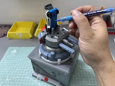
Painting
Coloring
Drilling
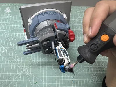
Polishing
Polishing
Documentation (1)
Assembly Guide (1)
组装说明(Assembly Instructions).pdf
License
This user content is licensed under a Standard Digital File License.
You shall not share, sub-license, sell, rent, host, transfer, or distribute in any way the digital or 3D printed versions of this object, nor any other derivative work of this object in its digital or physical format (including - but not limited to - remixes of this object, and hosting on other digital platforms). The objects may not be used without permission in any way whatsoever in which you charge money, or collect fees.
Comment & Rating (0)