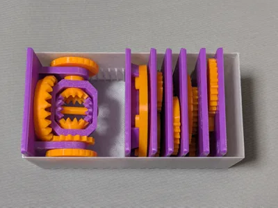
Differential Gear - Educational model


Print Profile(2)


Description
My Educational Mechanical Examples Series
This model is one of my educational mechanical mechanism examples on 80mm x 80mm base plates.
You can find all models of the series in this collection => [Mechanical Mechanism Examples]

This model
This is an educational model of the Differential Gear.


Brief Description

The most typical application of a differential gear is in the axle of an automobile. The driving wheels of a car are rotated by the engine’s power, but the key problem that the differential solves is that the left and right wheels do not always rotate at the same speed. When a car turns, the outer wheel must travel a longer distance than the inner one, meaning it must rotate faster. The differential gear allows this difference in wheel speed while still smoothly transmitting power from the engine.
In this model, the crown gear at the bottom acts as the power input, while the two side disks serve as outputs. The rotation of the crown gear is transmitted through a spur gear to the central gearbox, causing the entire gearbox to rotate. When when both sides experience equal resistance or no resistance, the disks rotate together at the same speed as the gearbox.
However, when one of the disks is subjected to greater resistance, its rotation slows down, while the other disk speeds up.
To understand why, try rotating the two disks in opposite directions: in that case, the gearbox itself does not rotate. If one side is turned faster than the other, the gearbox begins to rotate proportionally to that difference. This behavior is the origin of the name “differential” gear.
The key point is that, from the gearbox’s perspective, the two side gears always rotate at equal speeds but in opposite directions. Therefore, when the gearbox rotates, the average of the left and right wheel speeds exactly equals the rotation speed of the gearbox. As a result, by rotating the crown gear and driving the gearbox, the differential mechanism makes it possible to transmit power while controlling the average rotational speed of the two output shafts, even when their speeds differ.
Case
This model is compatible with the case included in my first set.

Printing
- Use the models named ???-printable.stl for printing.
The models named ???-assembled.stl are provided just to show how they should be assembled.
- Use well-dried PETG to have better dimensional accuracy.
- Use 0.1 mm or 0.08 mm layer height to have smoother surfaces.
- Use slow printing speed for overhangs.
- Select “Random” seam position to have smoother rotation.
Randomly distributed seam should be easily worn out after some wearing.
Sanding and Filing
Sometimes, the gears suffer from the stringing effect and/or elephant foot effect, resulting in a too tight fit to the shafts (they are designed with a 0.15 mm radial clearance).
If you see rough surface on the shafts due to stringing, sand off the roughness with a small piece of sand paper.


If you feel the gears do not rotate smoothly due to an elephant effect, widen the hole slightly by using a thin round bar file.

Without those issues, the parts should rotate very smoothly with minimal friction.
Assembly
No glue is needed, in theory.
First, put the output bevel gears in the gear box.

Then, slide the other two bevel gears simultaneously into the gearbox from the opposite sides. Once the gears are roughly meshed, you can swallow and align the small bevel gears to their correct positions by turning both output shafts in the same direction at the same time. Temporarily attaching the output disks to the shafts may make it easy to rotate the shafts for the purpose. This will be the most difficult part of assembly. If they do not get in, you can try slightly sand off the back surface of the small bevel gears.


Then, push the shaft in and fix it with the retaining rings.

At this point, check that the two output shafts can rotate smoothly. If the clearances are properly maintained, you should see that when you spin an output shaft quickly and release it, it continues to rotate slightly by inertia. If the rotation is not smooth, inspect the holes for the gear shafts, as well as the thickness and smoothness of the back-surface of the two small bevel gears. It is affected by the precision of the first layer height and the roughness of the bed floor. If necessary, adjust them carefully with a thin bar file or sandpaper before proceeding.
The rest is easy if the parts are nicely printed:
- Mount the spur gear on the side wall of the gearbox with a tab. The tab should fit the notch on the spur gear.
- Mount the spacer ring on the other side.
- Snap the side output disks into the rectangular holes at the ends of the shafts.
- Put the crown gear on the base plate and lock it with the retaining ring.
- Finally, push the shafts of the gearbox into the bearing on the base plate.

POSSIBLE DIFFICULTY: Inserting the side disks and mounting the two shafts onto the bearings can be a bit tricky, because the snap tabs and bearing parts may print somewhat fragile if your filament has absorbed moisture. Be careful not to break them during assembly.
In particular, if your print shows stringing, it’s a clear sign that the filament has taken up too much moisture or nozzle temperature is too high. So, dry the filament to get robust print.
Other educational models
You may also be interested in the models in my educational mechanical mechanism examples.
Find them in this collection:
https://makerworld.com/collections/15048577-my-educational-mechanism-models
Acknowledgement
I got into gears thanks to K.$uzuki's amazing articles and YouTube videos. Many of the mechanisms shown in this series came from the introductions on his website. He also makes excellent gear models himself. This series wouldn’t have existed without his inspiration.
I learned a lot about technical detail of designing gear tooth profiles from Haguruma-No-Hanashi website. I’m truly grateful for that.
License (2026-03-13 updated)
- The 3D model(s) are licensed under Creative Commons Attribution 4.0 International. (unchanged)
- However, the text and images on this page are copyright reserved. (added on 2026-03-13)
Comment & Rating (15)