Adjustable Pitch Airplane Propeller


Print Profile(2)


Description
Membership
Want to support me or sell my models? Join here!
About:
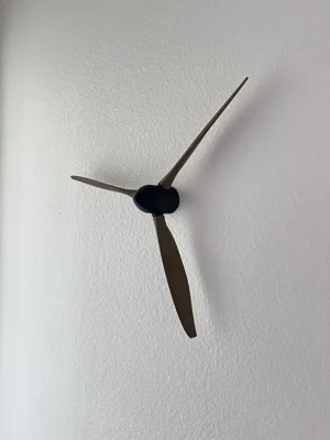
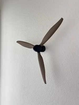
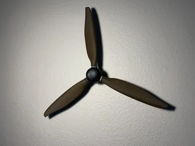
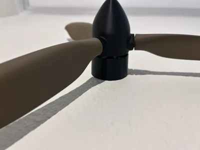
This is an airplane propeller that has adjustable pitch while still being able to spin! Unfortunately, it is not completly accurate to the real thing due to lack of hydraulics lol. It measures about 420mm x 420mm when fully assembled.
Push and pull the nose to change the pitch.
Enjoy!!
Note: Due to the size of the blades, I don't think it is a1 mini compatable.
Assembly Instructions :
- 3 screws are required if wanting to be mounted
- Super glue is optional but can be used
- Small pliers and scissors may help
Choose between:
Step 6 : No wall mount
or
Step 7 : Wall mount
Step 1: All materials + 3 Screws

Above is all parts needed plus screws.
Step 2: Nose and Blades
Gather the 3 blades and the nose, 
Screw them in just a bit so they stay in place as shown above.
Step 3: Pin Installation (Moderate difficulty)
Gather materials above

Slide the start of the pin into one of the propellers making sure to allign the notch. But don't push it all the way in.

Slowly thread the propeller in, while stopping to push in the pin more so it doesn't collide with the nose. As shown below, the blades of a scissor may help to push in the pin. 
Fully assembled, it should look how it does below. Notice how there are still some threads exposed at the ends. The pin should not be in contact with the nose. 
Step 4: Linkage 

Gather the above materials, the filament can be this size or a bit longer, and can be trimmed later. 
Put the linkage arm into the pin, there are two sides the the linkage arm, notice how the distance from the hole to top is shorter on the side outside of the nose cone. Make sure it is like this. The picture above shows the short gap up on the linkage arm.
Slide the filament peice into the pin and through the linkage arm. Push it through the other side of the pin, but just a little. The purpose of the filament going all the way through and a little bit more is to prevent the blades from over rotating.
The picture below shows the amount the filament should go through on the right side. 
Repeat for the other two blades. The ends of the filament close to the middle of the nose can be trimmed if desired.
Note how the pins are all below the corner peices that stick out on the nose, this is crucial. 
Step 5: Linkage pt 2
Gather above materials.
Filament should be the length as shown below or a little longer.
Place the linkage base onto the rod/shaft as shown below. 
Put the longer side of the shaft into the nose as shown below. 
Then put the filament into the linkage base through the linkage arm as shown below. 
Step 6 : No wall mount 
Gather above materials. 
Place the cover on the mount as shown below. Then insert the rod into the mount making sure the press all the way down. Super glue can be used to keep the rod into the base if necessary. 
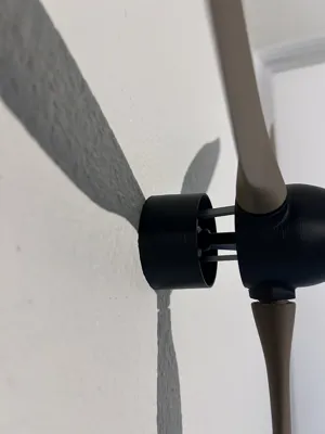
Step 7 : Wall mount 
Gather the same materials in step 6 but instead, mount the base to the wall and put the cover on as shown above. 
Then place the shaft into the base, glue can be used on the rod to keep it in place if desired.

YOUR FINISHED!!
Push and pull the nose to change pitch!
Thank you for your support, and I hope you enjoy!
License
You shall not share, sub-license, sell, rent, host, transfer, or distribute in any way the digital or 3D printed versions of this object, nor any other derivative work of this object in its digital or physical format (including - but not limited to - remixes of this object, and hosting on other digital platforms). The objects may not be used without permission in any way whatsoever in which you charge money, or collect fees.
Comment & Rating (17)