
Fara-Mox
Print Profile(1)

Description
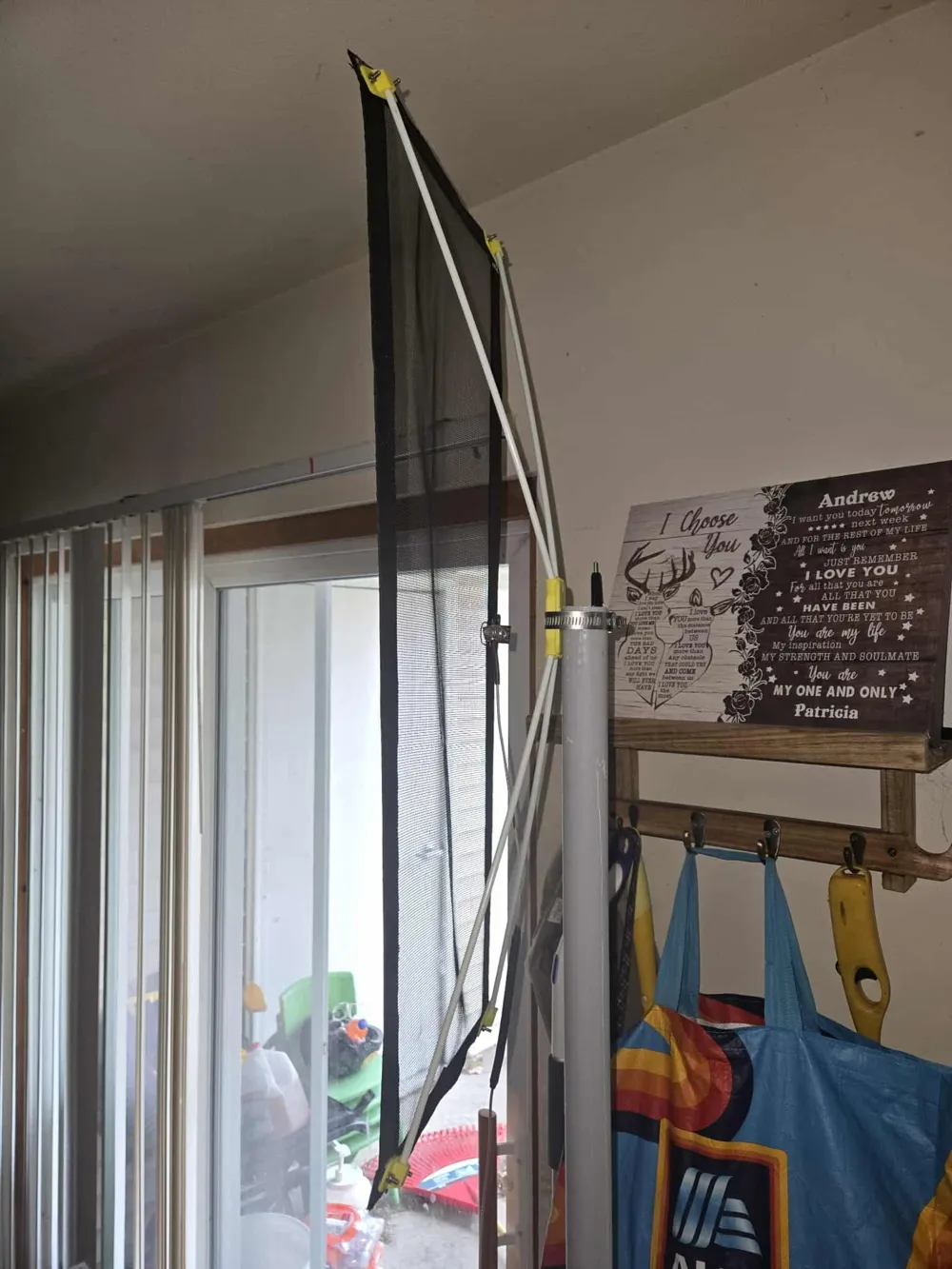
A 2 meter moxon antenna for ham radio.
Bill of materials:
Fiberglass or plastic mesh window screen
Two inch adhesive edge reinforcing webbing
four 5mm x 420 mm fiberglass rods
1.5 inch webbing to make rod pockets
1 inch emf tape
polyester thread
#12 polyester thread
1x bnc connector (https://makerworld.com/en/models/1961048-bnc-connector-mount#profileId-2107879)
All stainless:
10x m3 x15mm buttonhead screws
12x m3 washer
10x m3 (split)lock washer
10x m3 nut
2x m3 x 10mm buttonhead screw
Based on VE6SFX's design:
1. Basic wavelength
λ (meters) = 300 / f (MHz)
(or more precisely 299.792 / f for exact c, but 300 is fine for HF/VHF)
All linear dimensions of a Moxon (or almost any antenna) scale with wavelength.
2. Resonance scaling
When an antenna resonates at a measured frequency f_measured but you want it at f_target:
scaling_factor = f_measured / f_target
New dimension = old dimension × scaling_factor
Example: first build resonated at 140 MHz, target 146 MHz → factor = 140/146 ≈ 0.9589 → shrink everything by ~4.1 %
This works because resonant frequency ∝ 1 / physical size for a given design.
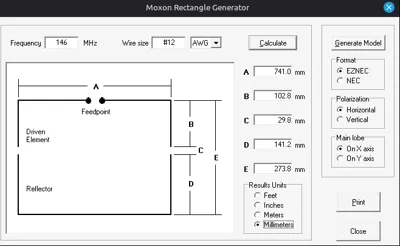
3. Standard thin-wire Moxon proportions (free-space, ≈50 Ω)
These are the classic empirical ratios (from L. B. Cebik W4RNL and most calculators like MoxGen for #12–#14 wire):
At design frequency f MHz, λ = 300 / f
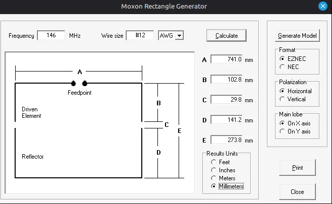
A (long parallel sides) ≈ 0.360 × λ
B (driven stubs) ≈ 0.052 × λ
C (gap) ≈ 0.014 × λ
D (reflector stubs) ≈ 0.072 × λ
E (reflector long side) ≈ 0.132 × λ
Original calculator used slightly different numbers because it includes a small velocity-factor correction, but they are within ~1–2 % of these.
4. Fat-element / flat-tape correction
When you use wide/tubing/tape elements instead of thin wire, the antenna becomes electrically “fatter” → resonance drops and feedpoint Z drops → you need:
Slightly shorter overall dimensions
Significantly larger gap C to keep feedpoint Z near 50 Ω
Rule-of-thumb used by most modelers (EZNEC, 4nec2, MoxGen users):
Equivalent round-wire diameter ≈ tape width / 2
(1 inch = 25.4 mm tape → model as ~12.7 mm / 0.5 inch diameter wire)
That’s why the vp9kf calculator with 12.7 mm gave C = 17 mm (too small for real tape) and we had to open the gap by trimming + add the hairpin.
Some builders use diameter ≈ tape width × 0.95 or even tape width itself, but width / 2 is the most common conservative starting point and matched.
5. Hairpin (beta) match stub approximate formula
The hairpin adds inductive reactance +jX to cancel the capacitive reactance –jX of a slightly short driven element.
Rough starting length (each leg) in cm for 2 m with ~2 cm leg spacing and thin magnet wire:
Leg length (cm) ≈ 1800 / f (MHz)
(1800 / 146 ≈ 12.3 cm starting point — we started way shorter because the antenna was only a few MHz high and the spacing was tight, so lower Z0 → shorter stub needed)
More accurate (if you have the driven-element reactance X from a VNA):
Inductance needed L (nH) = |X| / (2πf)
Then stub length l ≈ (arcsin(required X / Z0)) × λ / (2π)
Z0 of the stub ≈ 276 × log10(2S / d)
where S = center-to-center spacing of the two wires, d = wire diameter.
With 2 cm spacing and thin magnet wire, Z0 ≈ 350–400 Ω, so very short stubs (a few cm) give the small +jX needed when the antenna is only 3–4 MHz high in frequency.
In practice on 2 m everyone just starts around 3–6 inches (7.5–15 cm) total wire and trims 5 mm at a time.
6. Quick “fold-back” capacitive loading
If the antenna is too high in frequency, fold back length L at each end:
Approximate frequency drop ≈ (2L / λ) × 100 % of original frequency
(20 mm fold on each of four ends ≈ 3–5 MHz drop on 2 m)
So, our working recipe:
1. Model to thin-wire dimensions
2. Scale down ~3–5 % for tape
3. Open gap C to 40–55 mm (1.6–2.2× tape width)
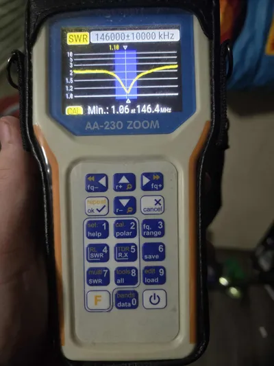
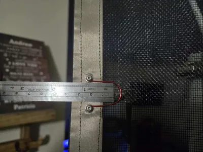
4 .If still a little high, add ~30–40 mm hairpin and trim to taste
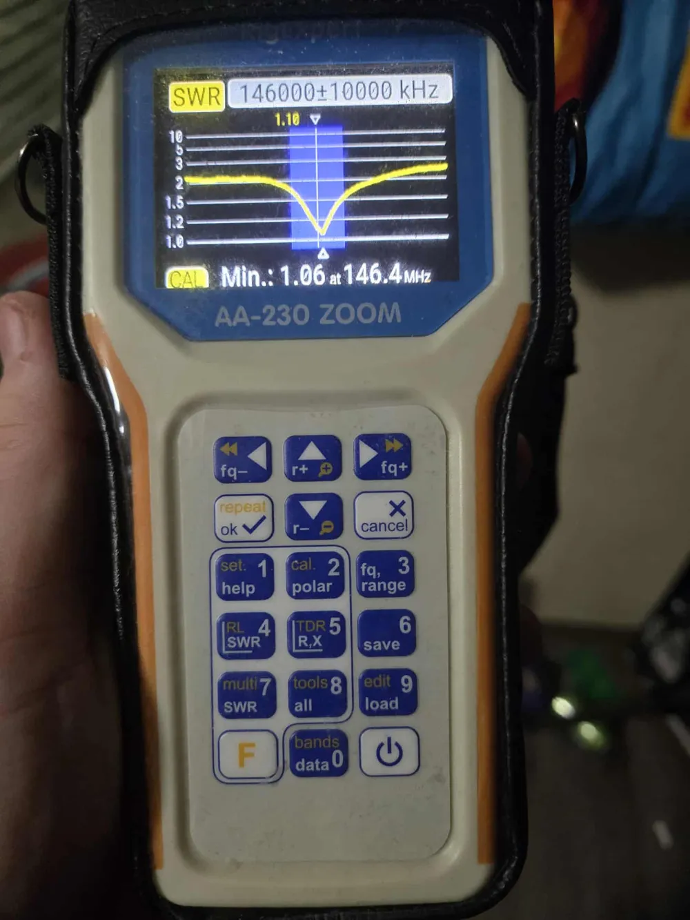
This should get swr to ~1.2 most of the time with 1 inch tape.
In cm:
- A ≈ 0.360 × 205.48 ≈ 74.0 cm
- B ≈ 0.052 × 205.48 ≈ 10.7 cm
- C ≈ 0.014 × 205.48 ≈ 2.9 cm
- D ≈ 0.072 × 205.48 ≈ 14.8 cm
- E ≈ 0.132 × 205.48 ≈ 27.1 cm
Construction:
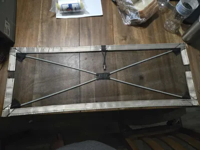
Trim the fiberglass rods to 350mm
Cut screen to 740 x 271 mm
Cut two strips of edge tape 740mm long
Cut two strips of edge tape 271mm long
Cut faraday tape:
1 strip 740mm long (mark this strip F)
2 strips 107 mm long (mark these strip B)
2 strips 148 mm long (mark these D)
2 strips 370mm long (Mark these each A)
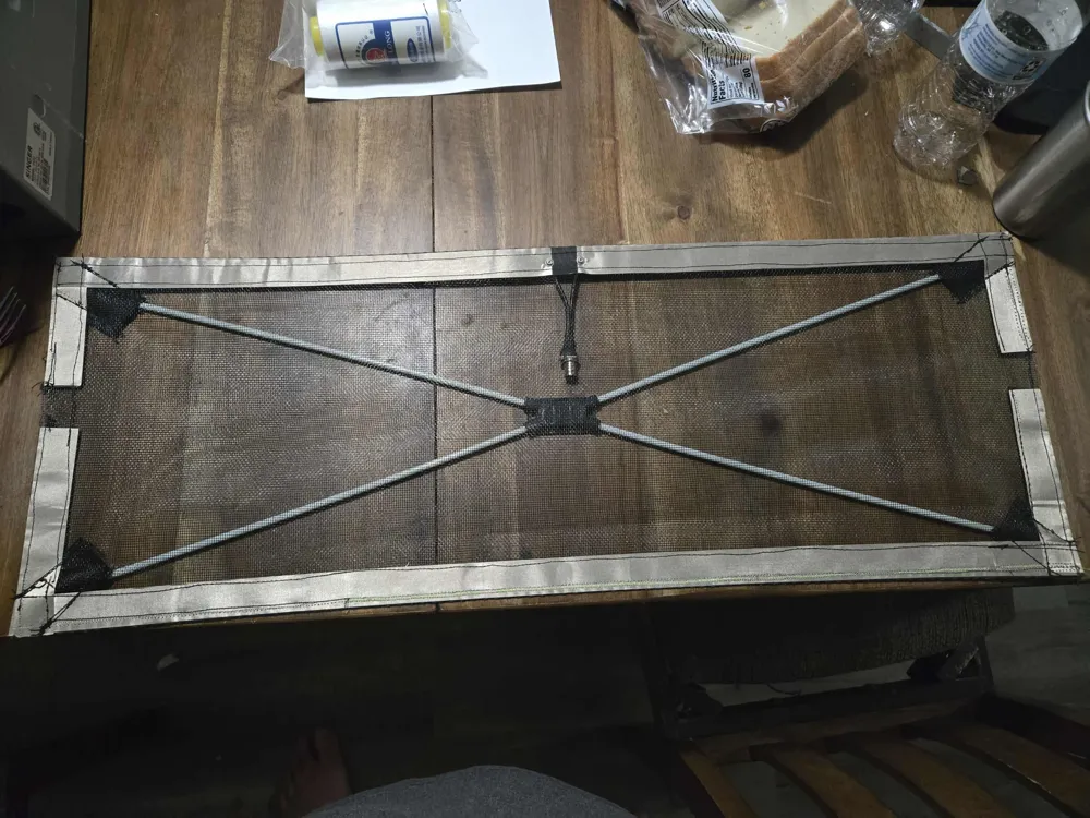
Apply the edge reinforcing tape halfway over the window screen. The tape backing is split peel only one half of it off for this.
Remove the other half of the backing paper and fold it over the edge and stick it down to the other side of the screen. It's okay for the corners to overlap this reinforces them further.
Apply Faraday tape strip F along the bottom.
Apply tape d on the left and right overlapping the bottom strip
Apply strips A horizontally along the top, starting in the corners. There should be about a 10mm gap between them.
apply strips B along the left and right vertically to form gap c which should be about 29mm
At this point, you sew the tape down to the webbing using a polyester braided thread about 12 weight (polyester is UV resistant)
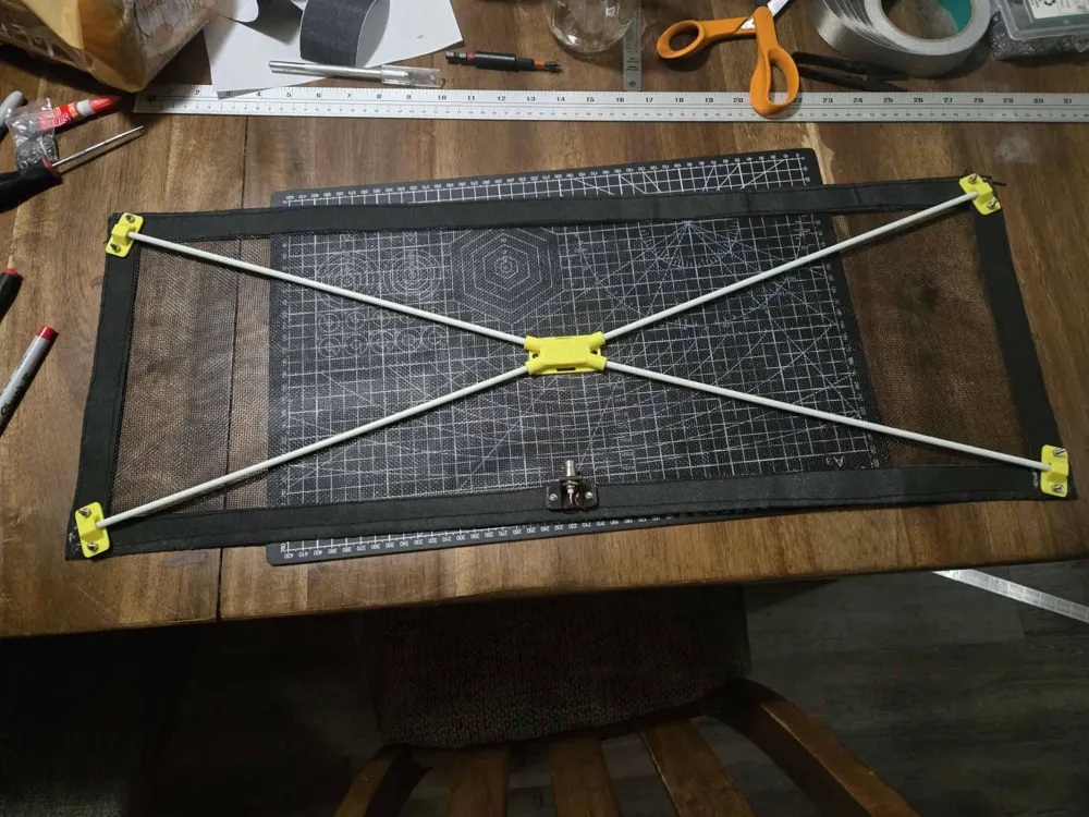
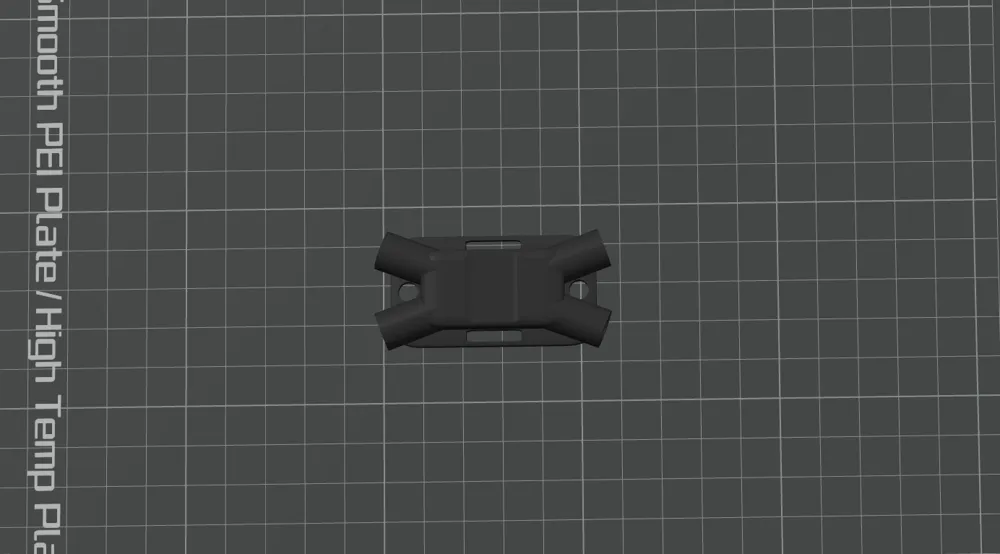
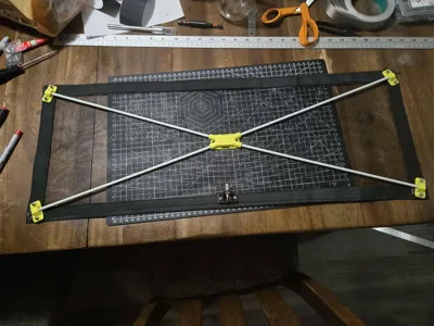
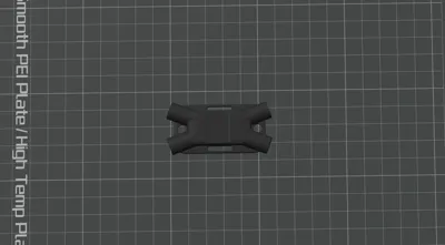
Insert the rods into the center x fixture and lay it down over the antenna and center it. add the corner parts.
Use a 3mm awl to poke holes where you want the screws to pass through the webbing. Using a power drill to spin the screws through the holes works the best but can be done manually. after that just bolt the parts on.
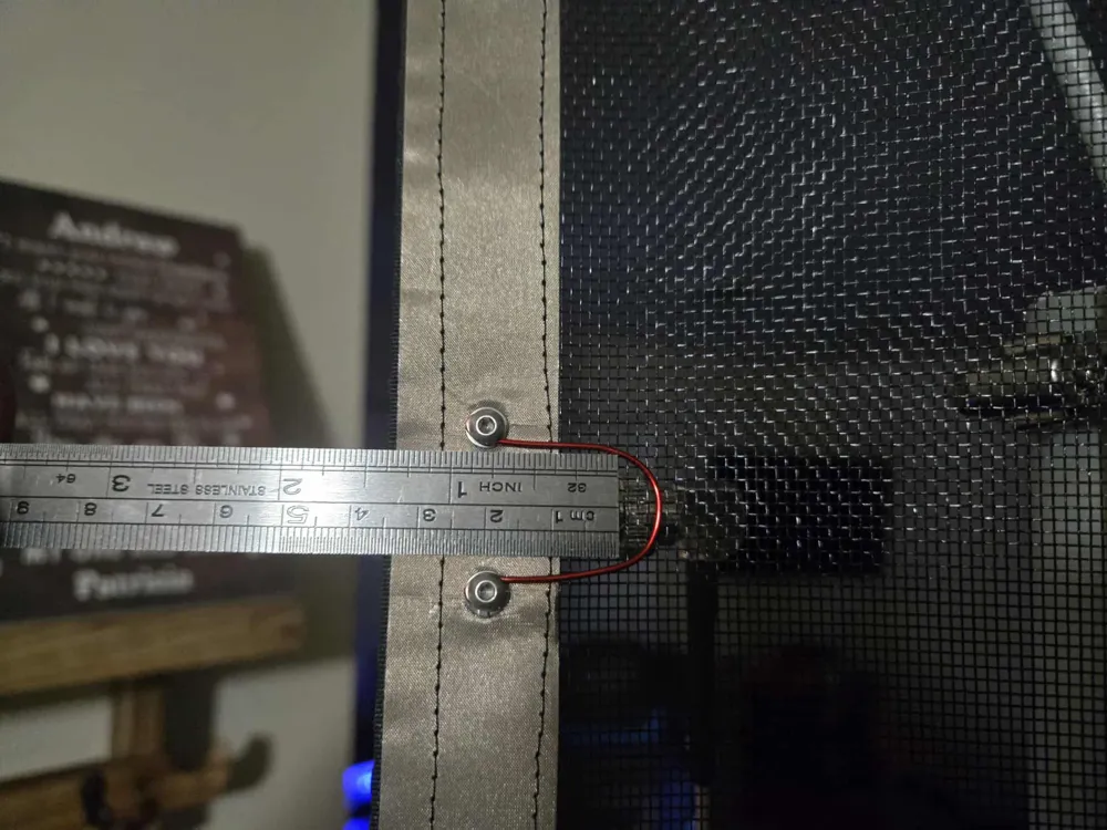
The feedpoint is the same, just loop the magnet wire from the bnc connector around each screw like an electrical terminal. you can use additional washers here to ensure a good connection so the wires are pinned between the washer and the bottom of the bnc mount.
The tuning stub is attached the same way, just slightly loosen the screws and smash it between the washer and the head of the screw once you get the match correct.
License

You may create derivative works based on this object, provided that all such derivative works are published exclusively on the MakerWorld platform and include proper attribution to the original creator. You may not share, upload, host, distribute, or publish this object—or any derivative work of this object—on any other digital platform, marketplace, or distribution channel. Commercial use of this object and any derivative works is strictly prohibited. This includes, but is not limited to, selling, renting, sublicensing, or using the object in any context in which you receive monetary compensation or other financial benefits.


Comment & Rating (0)