(CyberBrick Aid) Internal Battery Charging Mod


Print Profile(1)

Bill of Materials
.png)
Description
Please make sure you read all the instructions. Think of these solutions as ideas, and feel free to use or adapt them based on your own model's setup. I am not responsible for any negative outcomes from using these methods.
You don't have to stick to the exact steps for each solution. After you understand all of them, you can absolutely pick and choose methods from each one and combine them to create a solution that works best for you.
Solution 1: Use an "XH2.54 1-female to 2-male" splitter cable. The name for this part might be different in your region, so please refer to the image below. (This is the lowest-cost option, the parts are easy to buy, it's simple to do, and the logic is clear. It's an easy way to modify your existing model's charging method, but it has risks!)


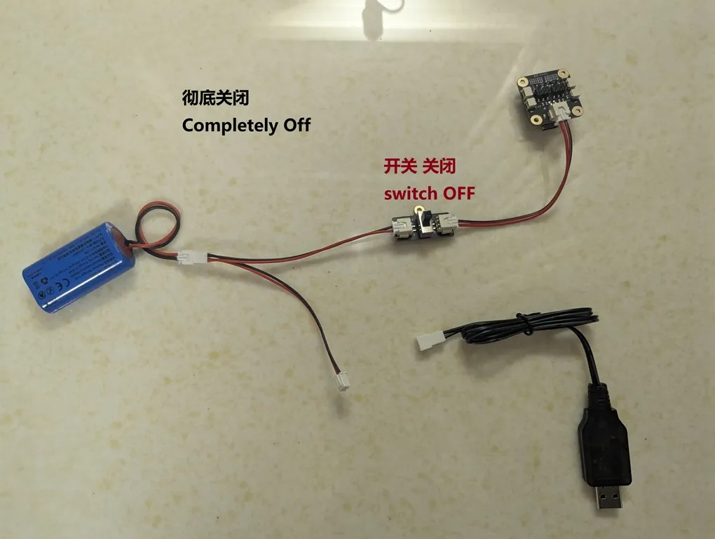
Related Risks:
- Scenario 1 (When charging the battery): You MUST make sure the main power switch for the "model circuit" is turned OFF.
- Scenario 2 (When the model circuit is on): You MUST make sure the battery's charging cable is unplugged. In other words, charging the battery and running the model circuit must never happen at the same time! This is just a simple circuit; it doesn't have smart power-splitting features like a phone or laptop.
- Scenario 3 (When not charging or running): It's recommended to keep the "model circuit's" main power switch OFF.
- Scenario 4 (Important): You cannot use the charging equipment to directly power the model's circuit. The charger is only for charging the battery. The charger can only provide 500mA, but the model's circuit sometimes needs much more than 500mA. This could damage your charging equipment.
Solution 2: Introduce a Type-C port for charging and use a simple mechanical structure to block the battery's charging port when the model's main power switch is turned on.


Related Risks:
- You must use the charger head included with the CyberBrick kit (Input: DC 5V 2A, Output: 7.4V 500mA), plugged into any standard 5V USB-A port, like a 5V/2A phone charger or a computer's blue USB 3.0 port. If you use any other way to charge, please make sure you know exactly what you are doing.
- The custom Type-C cable you make can only be used to charge the CyberBrick battery. Never use it to charge any other device. This is a charging cable carrying 7.4V. Your other electronics probably use 5V or even less. Using it incorrectly could instantly and permanently damage those devices.
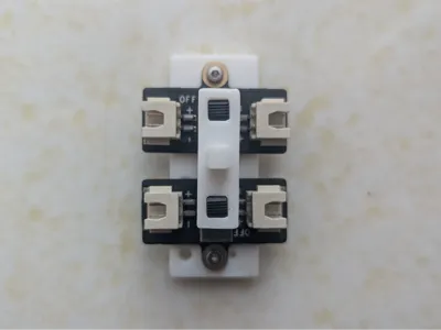
Solution 3: Add another switch (included in the CyberBrick kit, Product ID: XA007) to control the battery charging circuit. Then, use a "comprehensive switch" to link both the "charging circuit switch" and the "model circuit switch." Flipping this main switch will let you toggle between 'Operation Mode' and 'Charging Mode'.


Other Solutions: These are all options I've considered and use myself. They are well-suited for creating a more polished, complete solution to provide directly. However, I don't plan to make every friend who reads this learn all of them from scratch, to the point where we forget we're here to have fun.
- 6-pin micro-switch: Generally handles a lower current.
- 6-pin rocker switch: This looks like a great choice. With just a little bit of hands-on skill, you can get a fantastic result.
- Toggle switch: Also a good option, has a nice retro feel.
- Self-locking 6-pin push-button switch: Also very good, can handle larger currents, and can even have cool lighting effects.
- MOSFET module: This can be used for more complex situations.
Comment & Rating (3)