
H2 Series Dual Low Profile Ventilation System.
Print Profile(3)

Description
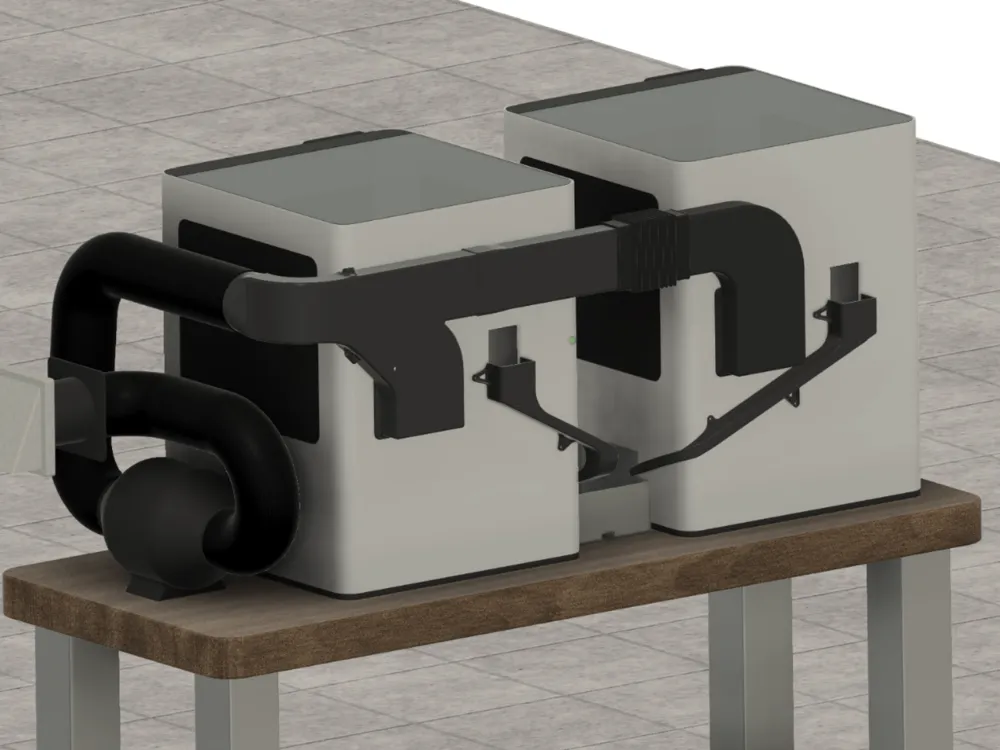
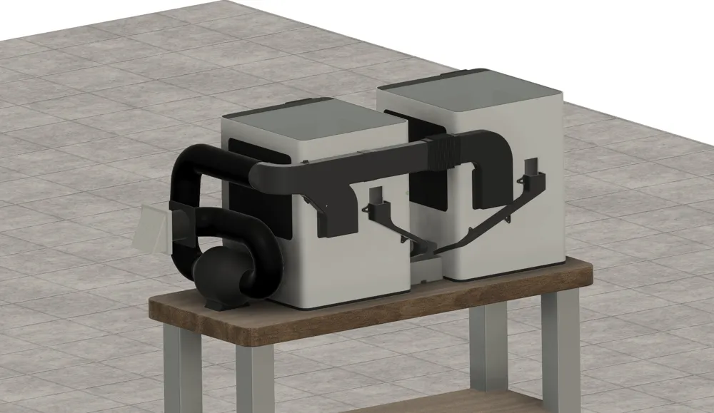
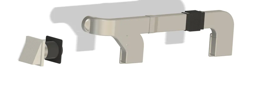
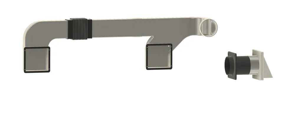
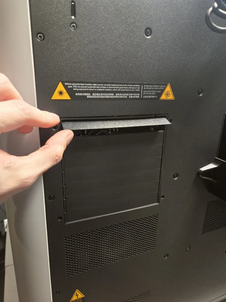
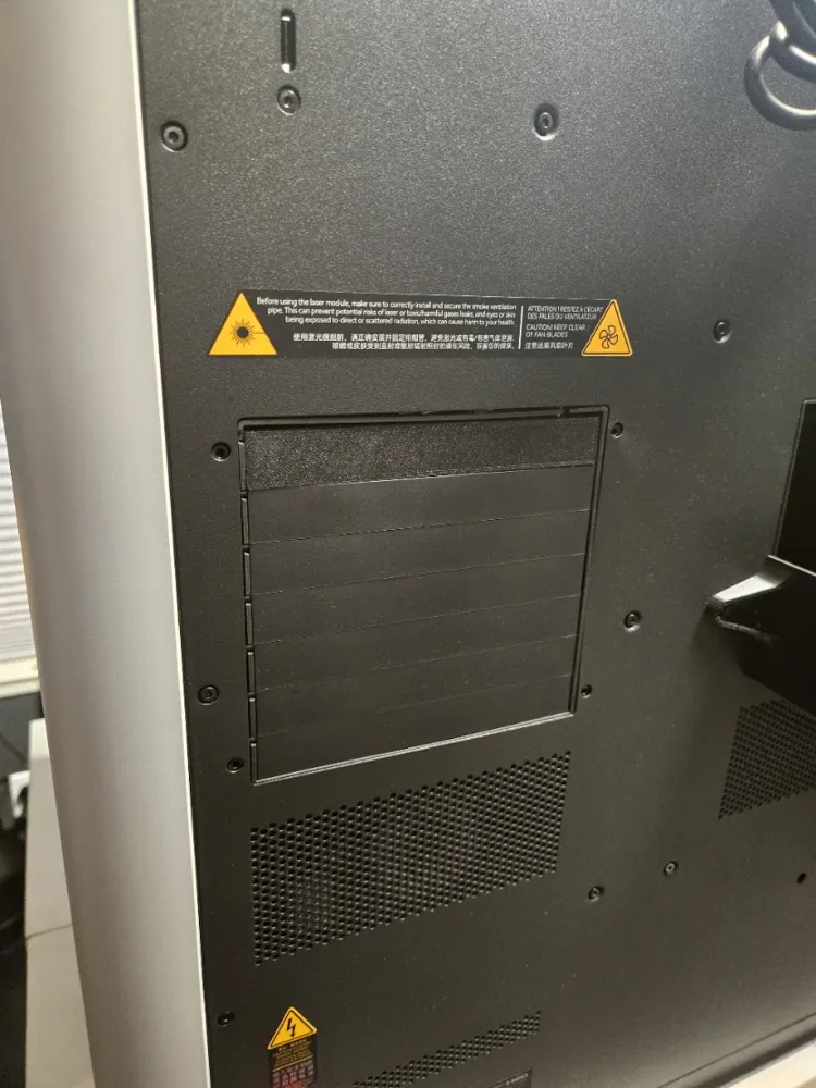
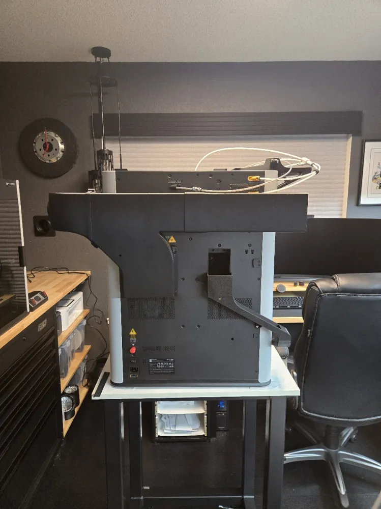
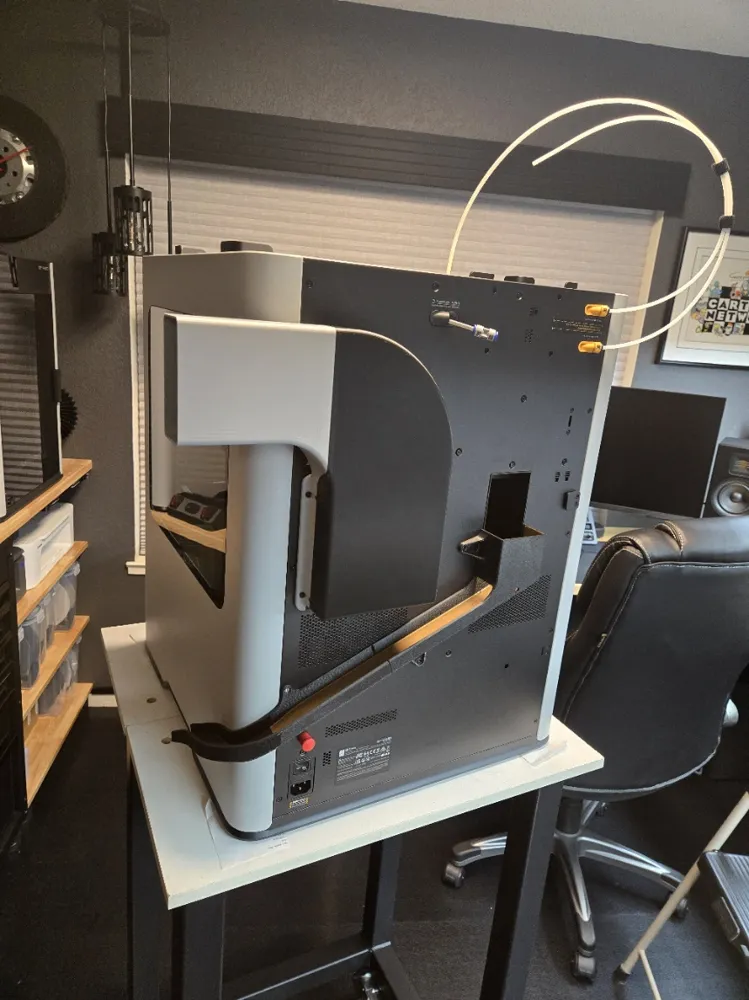
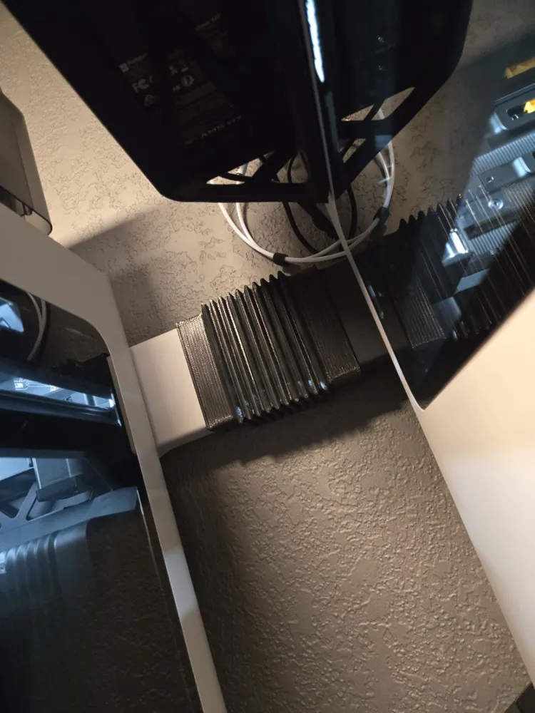
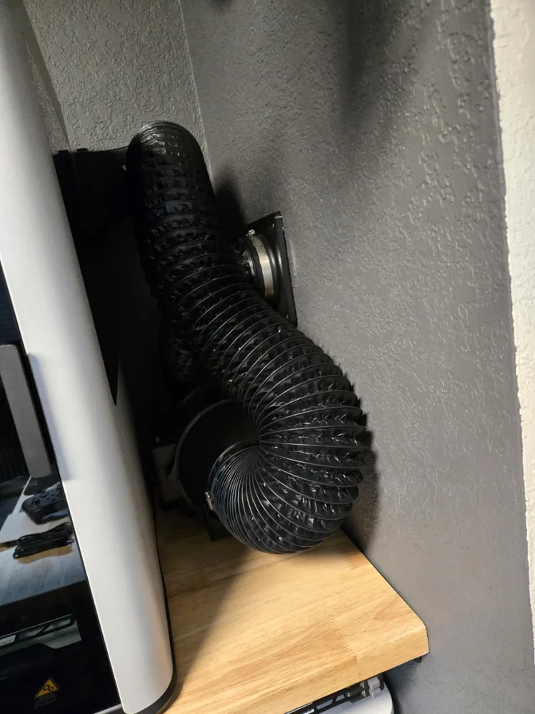
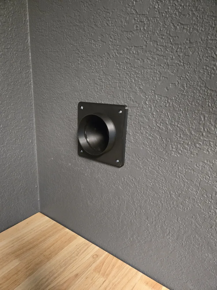
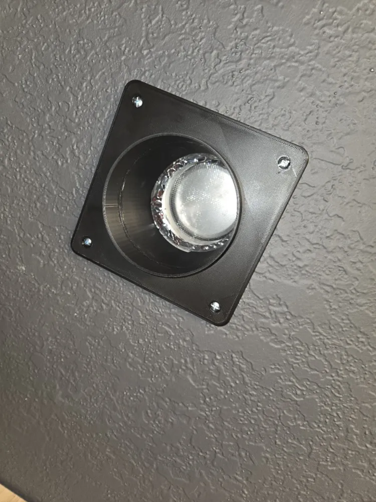
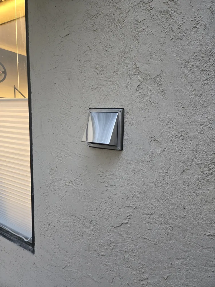
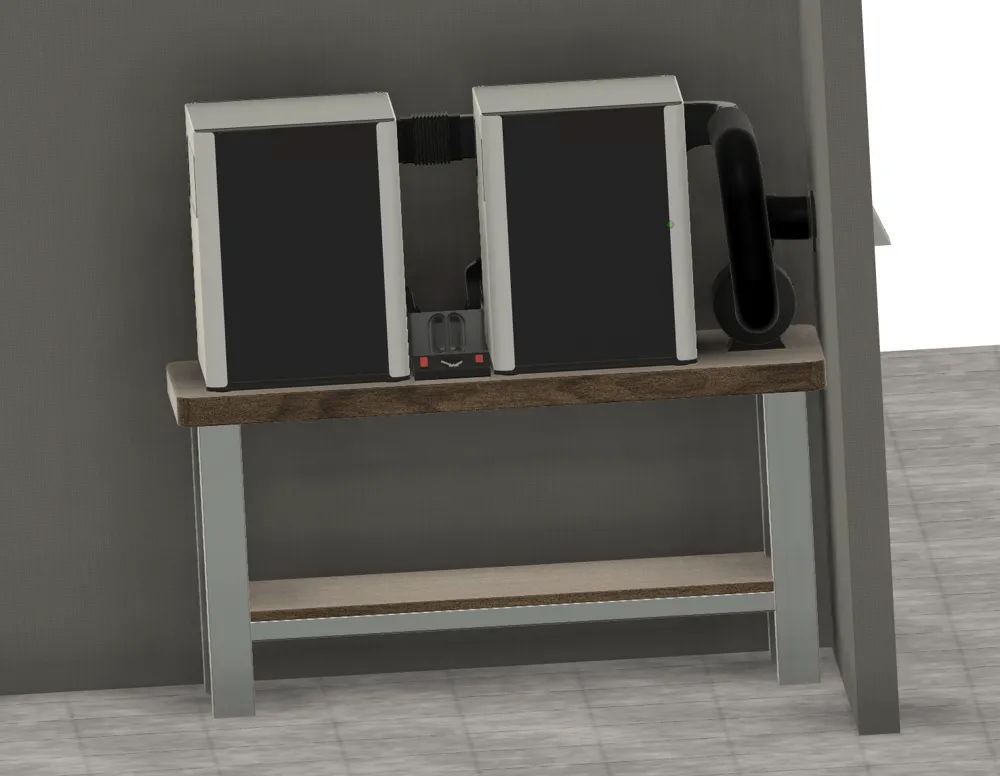
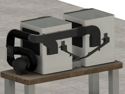
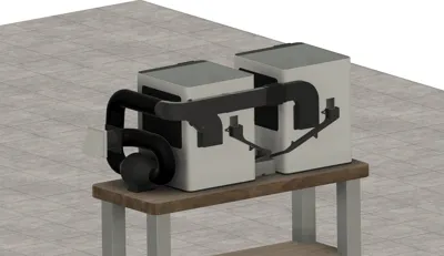
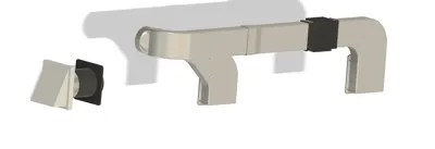
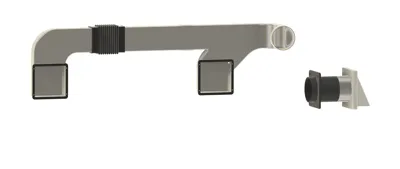
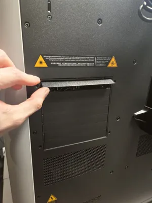
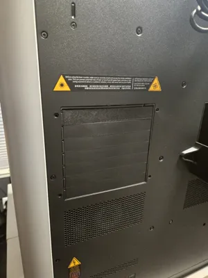
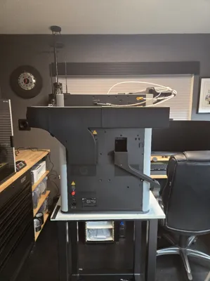
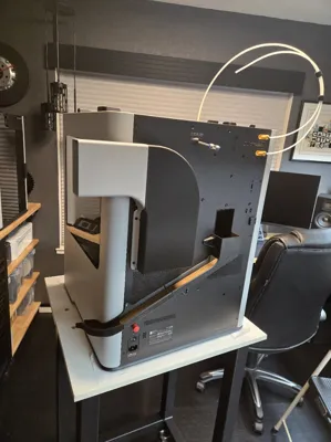
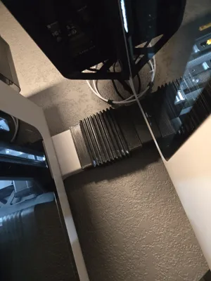
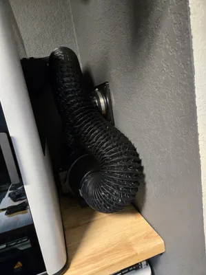
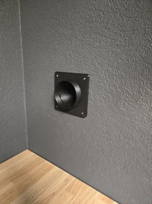
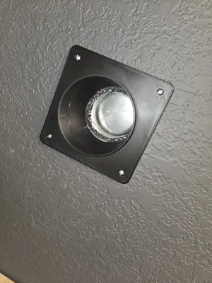
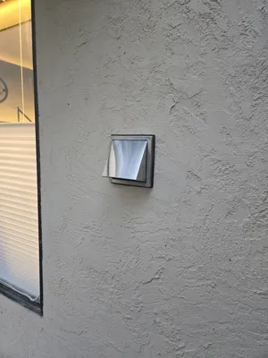
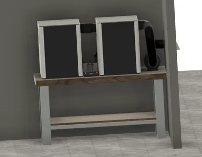
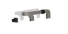
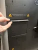
This system is designed to actively vent two H2 printers to the outside. It is designed to accommodate printers being very close to the back wall while still allowing maximum flow and flexibility between the printers both in vibration and distance. It connects to a 4 inch flexible duct and is intended to be fed through an in-line duct fan (I am using a AC Infinity CLOUDLINE A4) and have another design available to incorporate the controller for it. In order to make this system functional while printing in materials where the vents are closed, you must print the included replacement slat for the rear vent and replace the upper most slat so that it is sucked open passively by the duct fan. Alternatively you can also just remove one completely or cut the control arm off one of the OEM ones. In my testing, as long as you keep the fan speed low, it does not negatively effect the chamber temp but does a great job at evacuating the fumes. The duct pieces should be printed out of at least PETG, ASA would be even better. The flex joint section is printed out of 95A TPU, I have had the most success printing it at a 45 degree angle using PLA support material. The Exterior vent I used is from Amazon, it has a back draft sealed door but it was not sprung, so I made my own spring system which has been working great, if there is any interest in this I will add the parts to this upload. The interior wall bulkhead is designed to be printed in 2 parts and glued together, the inner wall tube piece can be adjusted in length to fit your thickness of wall. In my case it is sized for ½ in Drywall, 2x4 construction, a plywood sheer wall, and stucco/ mesh facing. TPU gaskets are provided for the bulkhead as well as the duct manifolds for each printer. To install the ducts to the printer, use BT3x12 screws for all but the one mounting hole that goes through the access hole in the right printer duct, for this one use BT3x16. The new version of the Right printer duct is split into two parts for printability. To bolt the two halves together you will need 2x M4 heat press inserts and 2x m4x20 countersunk bolts. The new bridge tube also includes a small recess for the left PTFE Buffer connection on the H2D, this is the piece that should be shortened or extended to change the distance between the two printers. To flip the system the other way, all the parts can be mirrored.
UPDATE 2/14/26:
I have added an updated revision to the design including a recess in the extension tube to avoid hitting the PTFE tube inlet, better geometry on the curved vent section, plus a bolt and flange system to bolt together the to large merge sections instead of needing to be glued (use m4 heat press inserts and countersunk bolts). The print profile also includes orientations and settings I have used for best results.
License

You shall not share, sub-license, sell, rent, host, transfer, or distribute in any way the digital or 3D printed versions of this object, nor any other derivative work of this object in its digital or physical format (including - but not limited to - remixes of this object, and hosting on other digital platforms). The objects may not be used without permission in any way whatsoever in which you charge money, or collect fees.


Comment & Rating (16)