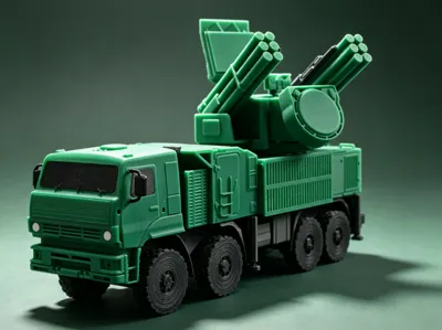
Pantsir-S1 Gun-missile integrated air defense system 1/72


Print Profile(1)

Description
Vehicle Introduction
The Pantsir-S1 (Russian: Панцирь-С1, NATO reporting name: SA-22 Greyhound) is a Russian-made gun-missile air defense system, designed to replace the previous generation 2K22 "Tunguska" system. It possesses independent combat capability while on the move, uses phased array radar for target acquisition and tracking, consists of an integrated missile and anti-aircraft gun weapon system, and is controlled by the same radar. In combat, it is used to accompany tank regiments and motorized infantry regiments, providing them with air defense services. Its theoretical range is a radius of 30 kilometers and an altitude of 15,000 meters, with a close-range radar effective radius of 5 kilometers, capable of simultaneously tracking 4 targets

Above from Wikipedia
In the game War Thunder, the Pantsir-S1 is a Rank VIII vehicle with a Battle Rating of 12.0. This model is mainly based on the War Thunder in-game model


Profile Description
The model is about 210mm long (oversized for 1/72 scale), consists of over 50 parts, with a movable turret and gun-missile system, and features many details. A maximum of four colors are needed for printing, with green and black being the main colors; the remaining two colors are used very little and can be ignored. No AMS is required for printing, and components of different colors are already arranged on separate plates

A total of 6 plates are required for printing, with the first 4 plates containing main components and the last two containing a small number of decorative parts

Plate 1 contains chassis components, including the main frame axles and retaining pins, to be printed in black
Plate 2 contains wheels, chassis decorative parts, cockpit decorative parts, and the gun, to be printed in black
Plate 3 contains the main superstructure components, to be printed in green
Plate 4 contains weapon system components, to be printed in green
Plate 5 contains headlight decorative parts, to be printed in white
Plate 6 contains rear bumper decorative parts, to be printed in gray
The print profile has already set up part bases and supports, and PLA can be printed directly
Boost Me (for free)
Designing is not easy; I hope to get everyone's support!
Assembly Steps
Tools Needed
- Tweezers
- Diagonal cutters
- Model glue
Chassis Assembly
- Install axles

Insert the left and right axles into the reserved holes and press firmly. Repeat 4 times to install all axles. No glue is needed for this step
- Install decorative parts

Install the battery and small fuel tank on the left side of the chassis, and the air intake on the upper left side
Glue is optional here; it can be used for reinforcement

Install the air tank and large fuel tank on the left side of the chassis, and the spare tire bracket and spare tire on the upper right side
Glue is optional here; it can be used for reinforcement
- Install retaining pins

Insert the retaining pins into the corresponding positions above the chassis. No glue is needed here
Install wheels
Install the wheels onto the already installed axles
Cockpit Assembly
- Install cockpit accessories

Install the windshield, side windows, and headlights onto the cockpit body. Glue is required here
It is recommended that the smooth side of the side windows faces outwards
Install side mirrors
Insert the side mirrors into the reserved slots on the side of the cockpit. Note that the mirrors may require trimming. No glue is needed here
- Install cockpit

Insert the protrusion on the bottom of the cockpit into the groove at the front of the main frame to complete the assembly. No glue is needed
Control Compartment Assembly
- Install control compartment accessories

Install the spare parts box, cable reel, top mesh cover, and side mesh cover into the front slots of the control compartment. Glue is required here
- Install control compartment

Insert the bottom slot of the control compartment assembly into the pins already installed on the main frame. No glue is needed
Turret Base Installation
- Turret Base Assembly

Insert the 4 bosses of the turret base into the reserved mounting holes on the mesh cover. No glue is needed here, but the mounting holes may require trimming with diagonal cutters
Install turret base
Insert the bottom slot of the turret base assembly into the pins already installed on the main frame. No glue is needed
Power Distribution Compartment Installation

Insert the bottom slot of the power distribution compartment into the pins already installed on the main frame. No glue is needed
Weapon System Installation
- Search Radar Assembly

Insert the search radar's lower pivot into the mounting bracket, press the mounting bracket firmly. Glue is required for the mounting bracket, but do not apply glue to the pivot

Insert the protrusion at the front of the search radar and bracket assembly into the turret slot. Glue is recommended
- Optical Measurement Equipment Installation

Directly insert into the top slot of the turret
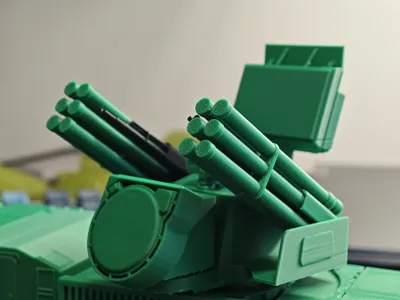
- Gun-Missile Installation

Insert the gun and missiles into the pivot base, then insert into the turret. Glue is required here
Ensure symmetry on both sides
- Baffle Installation

Use glue to install the baffles onto the side platforms of the turret
Ensure symmetry on both sides
Install weapon system
Insert the bottom slot of the weapon system assembly into the top of the already installed turret base. No glue is needed
Rear Bumper Accessories Installation

Directly insert the rear bumper accessories into the reserved slots on the rear bumper. No glue is needed
Boost Me (for free)
Documentation (1)
License
You shall not share, sub-license, sell, rent, host, transfer, or distribute in any way the digital or 3D printed versions of this object, nor any other derivative work of this object in its digital or physical format (including, but not limited to, publishing derivative works outside the Makerworld platform or hosting on other digital platforms). The objects may not be used without permission in any way whatsoever in which you charge money or collect fees. Subject to the above restrictions, derivative works may be published only within the Makerworld platform, and all such derivative works must be licensed under the same SDFL‑C license, without modification or additional terms. You may download the digital versions of this object, 3D print it, and display images, videos, or usage demonstrations of 3D printed versions of the object on personal social media platforms or Makerworld official channels, provided that no digital versions of the object are shared or distributed.
Comment & Rating (9)