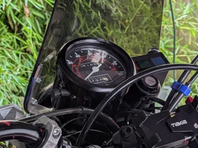
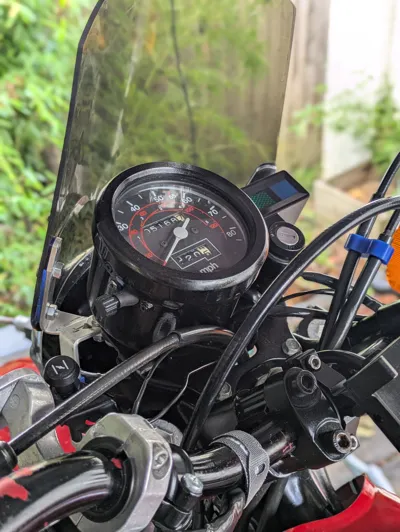
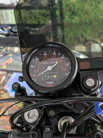
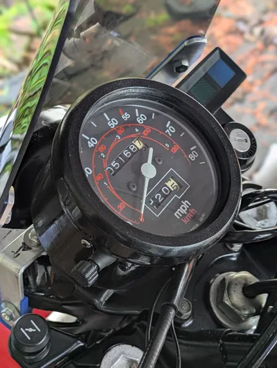
1981 Honda Xl250S Speedometer Body


Print Profile(1)

Description
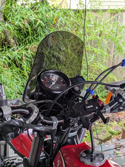
This Is a replacement speedometer housing for the 1981 Honda xl250s, but will probably be compatible with earlier models as well.
NOTE: this model is NOT a new speedometer and requires multiple components from the original housing. It is meant to be an alternative to replacing the whole unit if only the plastic housing is damaged/worn.
With that said, the components required from the original speedometer housing are:
-Glass screen (it is retained by a metal piece that crimps down around it which must by carefully removed)
-Glass screen gasket
-Light diffuser (small metal cylinder that sits above the bulb)
-Trip set rubber boot
-Speedometer (the metal mechanic assembly part)
Additional hardware required:
x4) m3x (I used the ones that come from Bambu to match the black plastic)
x1) m3x12
x1) m3x20
x2) m4x12 https://www.amazon.com/dp/B081DS3QVT?ref=ppx_yo2ov_dt_b_fed_asin_title&th=1
x10) m3 threaded inserts https://www.amazon.com/dp/B0BTYF2MMD?ref=ppx_yo2ov_dt_b_fed_asin_title
x2) m10x35 bolts
x2) m10 nylon lock nuts
x2) washers
Assembly:
~Pre Assembly~ Test fit all components primarily "Trip Set Screw"
- before assembly it is super important to test fit the trip set screw knob to the speedometer. I was never able to determine what kind of thread the screw goes on to; It's something m3, I was never able to determine the pitch and thus had to settle for a plastic on metal connection. The fit should be tight, but the dial should only turn when the screw is fully seated against the speedometer.
1: Set threaded inserts
- there are 8 in the speedometer body. 4 are around the top lip and the other 4 are inside the body to the sides of the hexagonal recesses where the larger bolts nest into. The last two are inserted into the “Trip Set Bracket”. It is important when setting the inserts into the “Trip Set Bracket” to seat them deep enough so that no part of the insert is protruding from the curved face. It is also important that they are set as straight as possible which can be a bit tricky with the curved face.
2: Glue Light diffuser in place
- Use an epoxy like JB Weld. Dab it around the two lips that hold the diffuser in place, then apply a small amount around the bottom of the diffuser where it will seat. I recommend doing a test fit before gluing to make sure the diffuser fits properly.
3: Fasten Larger Bolts
- Drop the two bolts into the hexagonal recesses then drop the "Bolt Retainers" on top securing them with m3x8 screws
4: Secure "Trip Set Bracket"
- Trim about 1/8"-3/16" off the end of the trip set screw boot. Insert the trip set screw rubber boot making sure it seats. next place the “Trip Set Screw Bracket” behind the boot and screw it in from the front using the m3x12 and m3x20 screws
5. Attach the Speedometer assembly
- place your old speedometer assembly inside the main body, making sure it seats nicely up against the slanted platform with the threaded part sticking out the hole. Secure it using the m4x12 screws on either side.
6. Attach the lid
- place the rubber gasket on the top lip of the speedometer body then place the glass screen on top of that. place the lid on top of that then secure it in place using the 4 m3x………screws. pressure may have to by applied to the top of the lid in order to get the holes to line up correctly.
7.Screw in "Trip Set Screw"
- Insert the “Trip Set Screw” into the rubber boot and turn counter clockwise until the trip set numbers begin to change, ensuring that it is seated correctly.
Make sure to check out my page for other Honda XL250s bits and bobs!
Comment & Rating (0)