


Print Profile(2)


Description
IMPORTANT FOR PRINTING: Paste the following gcode into your PLA profile under Advanced > Filament Start gcode. Your parts WILL warp if this isn't used.
; filament start gcode
; --- H2D chamber fan override 60 % ---
M106 P3 S155 ; P3 = exhaust/chamber fan, 155/255 ≈ 60 %
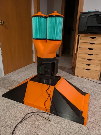
This is a laminar flow hood that fits only on H2 series printers. It is a printed 18" x 36" laminar flow hood designed to be mounted on top of a 2020 aluminum extrusion enclosure, but it can also be used horizontally. If this gains enough traction I may revisit it and document assembly further if needed. At the moment it is designed to use the following materials:
4kg of PLA
1.5kg of ABS
33g of PETG
32 M5x12mm SHCS
4 M5x16mm SHCS
36 M5 Hex Nuts
1 Vivosun G8 Fan
2 Rigid VF6000 Hepa Filters
1 Filter King 18x36x1 Air Filter
Lots of hot glue sticks (recommended) or caulking
1 soldering iron with a chisel tip
The 8 angled outer pieces should be assembled first. The flat PLA pieces slot over the ABS corner pieces. and are then secured with M5x12 screws and nuts. The flat top ABS part that interfaces with the fan is placed on top and then bolted into the 4 flat PLA parts with 20 M5x12 screws and 4 M5x16, One from the bottom up between each ABS corner piece and the middle ABS piece. The filter slot cover is then assembled with 2 M5x12 screws, as well as the bottom part of the filter slot (this may use M5x8mm screws).
The diffuser plate is then snapped together like a puzzle such that all the outer angled faces point up. This is the welded together with a soldering iron outside or in a well ventilated area. Weld the seams on both sides. The diffuser plate is placed into the upside down hood so that the angled faces meet. The diffuser plate is then hot glued around its perimeter to the inside of the hood (sorry this is jank, the diffuser plate unfortunately came after I decided I didn't want to reprint the hood for a third time due to its size.) You can now insert the 18x36 filter into its slot and snap the slot cover into place.
Now you put the fan insert into the downstream side of the G8 fan with the cone facing into the fan. The fan can now be inserted into the hood. Next you add the filter wye onto the fan's upstream side. You then place the two T shaped screws unto their inner slots in the wye with the screw going up. Then you add two of the printer nuts onto each screw and set the top nut to the same height as the bottom face of the top of the filter so that another nut can clamp the filter. This will require some trial and error. You want the nuts to be low enough to that the ring on the bottom compresses while still sandwiching the small 15mm ring at the top that the screw goes through. Once the height is set, add the top cones and then the final nuts to each filter and tighten down. Once fitment is good, hot glue where the filter and bottom two nuts meet to seal the airway created by the flat screw.
Hot glue anywhere that air passes through if there are any unexpected leaks or contamination of plates. Please feel free to add onto the design, request STEP files, or ask clarifying questions. I have yet to finish setting mine up but am close to doing so.
License
You shall not share, sub-license, sell, rent, host, transfer, or distribute in any way the digital or 3D printed versions of this object, nor any other derivative work of this object in its digital or physical format (including - but not limited to - remixes of this object, and hosting on other digital platforms). The objects may not be used without permission in any way whatsoever in which you charge money, or collect fees.
Comment & Rating (9)