Search models, users, collections, and posts

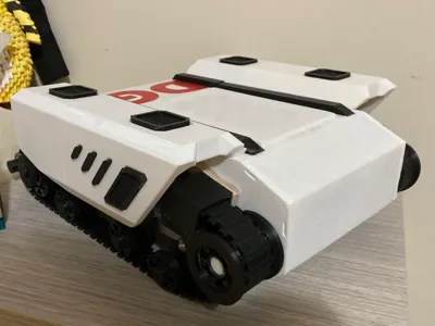
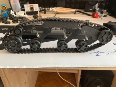
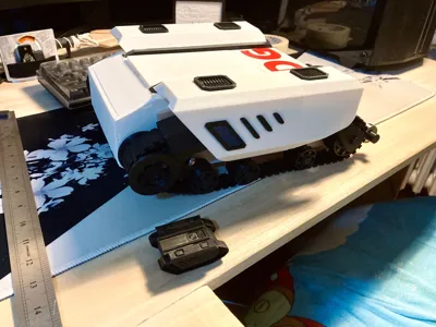
Tank
IP Report

Print Profile(1)

0.2mm layer, 6 walls, 25% infill
Designer
39.7 h
20 plates
Open in Bambu Studio
Boost
11
41
2
0
18
0
Released
Description
Content has been automatically translated.
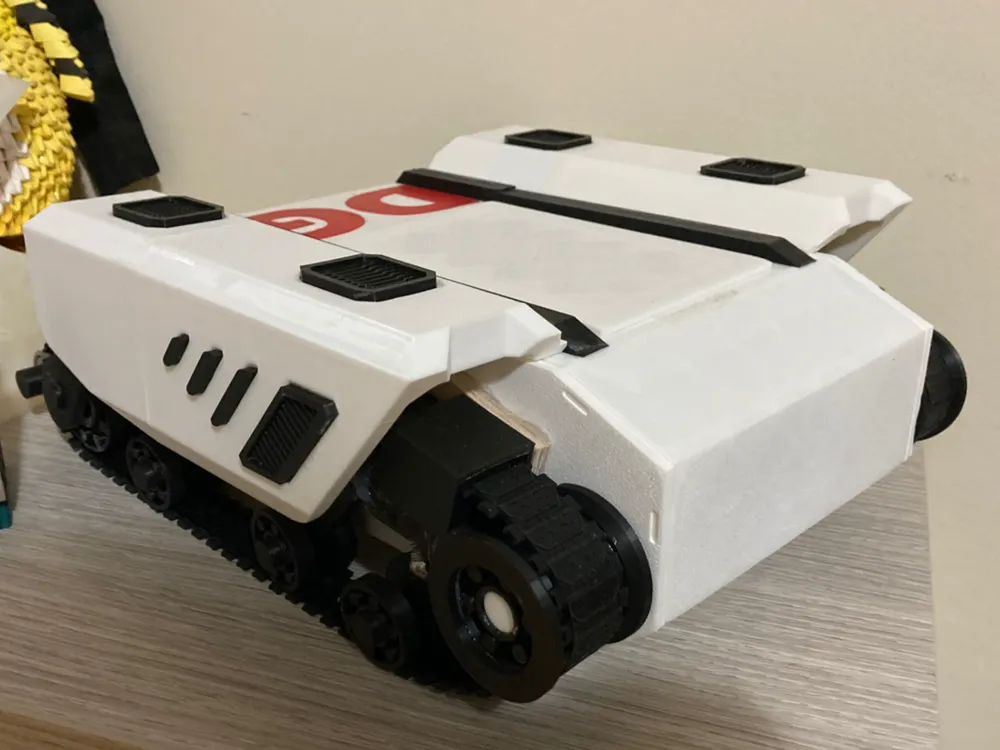
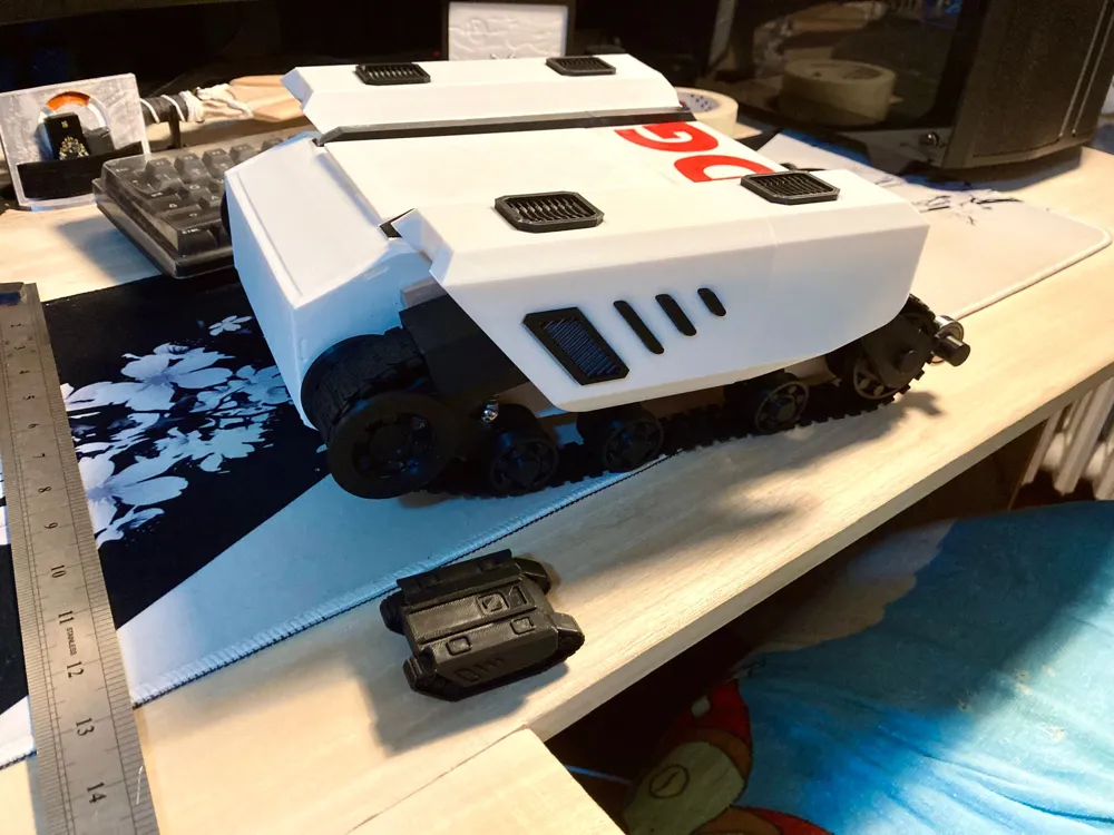
🚗 Project: Remote-Controlled Car with ESP8266, Arduino CNC Shield and DRV8825 Drivers
🔹 General Description
The project involves building a remote-controlled car controlled via Wi-Fi through a web interface, developed with ESP8266 and Arduino Uno + CNC Shield.
The system allows controlling the car's movements (forward, backward, right, left) by operating four NEMA 17 stepper motors (model 17HD48002H-22B) driven by DRV8825.
Power is supplied by a Li-Po 3S 11.1 V 2200 mAh battery.
🔹 Main Components
| Component | Function | Notes |
|---|---|---|
| ESP8266 (NodeMCU) | Manages Wi-Fi connection and web control interface | Creates a web server accessible from PC or smartphone |
| Arduino Uno + CNC Shield | Manages motor logic | Interprets signals from ESP and drives DRV8825 |
| DRV8825 Drivers (x2) | Stepper motor control | Current adjustment via trimmer, thermal protection, and microstepping |
| NEMA 17 Motors – 17HD48002H-22B (x4) | Car wheel movement | Connected to driver outputs A1–A2 and B1–B2 |
| Li-Po 3S Battery (11.1 V, 35C, 2200 mAh) | Main power supply | Provides power to the motors |
| Status LED (Wi-Fi) | Network connection indication | Lights up when the server is online |
| Breadboard and Dupont cables | Low current logical connections | For control signals between ESP and Arduino |
🔹 Functional Diagram (description)
- Power Supply:
- The 11.1 V Li-Po battery powers the “12–24 V” terminals of the CNC Shield (for the DRV8825).
- A parallel branch passes through the step-down, which provides stable 3.3 V to the ESP8266.
- All grounds (GND) are connected in common (battery, shield, ESP).
- Motor Control:
- The DRV8825 drivers receive STEP and DIR signals from the CNC Shield pins.
- The NEMA 17 motors are connected to the driver outputs A1–A2–B1–B2.
- Microsteps M0, M1, M2 are configured to LOW (full step).
- Communication:
- The ESP8266 acts as a web server: when the user accesses it via PC or iPhone, they can send commands to move the car.
- Commands are transmitted serially to the Arduino, which interprets them and activates the corresponding motors.
- Web Interface:
- An HTML page with directional buttons (↑ ↓ ← →).
- The buttons work with “mousedown” / “mouseup” events, allowing movement only when held down.
- Status LED:
- An LED connected to an ESP pin lights up when the module is connected to the Wi-Fi network and the server is active.
🔹 Operation
- Upon power connection, the ESP8266 connects to the Wi-Fi network.
- Once connected, it turns on the status LED and starts the web server.
- The user opens the web page from the browser and controls the car's movements.
- The Arduino receives commands and actuates the motors based on the chosen direction.
- The system is completely wireless and autonomously powered by the battery.
License
This user content is licensed under a
Creative Commons Attribution-Noncommercial-NoDerivatives


Comment & Rating (2)