
TRMNL Seeed DIY (OG) Kit Case
Print Profile(2)

Description
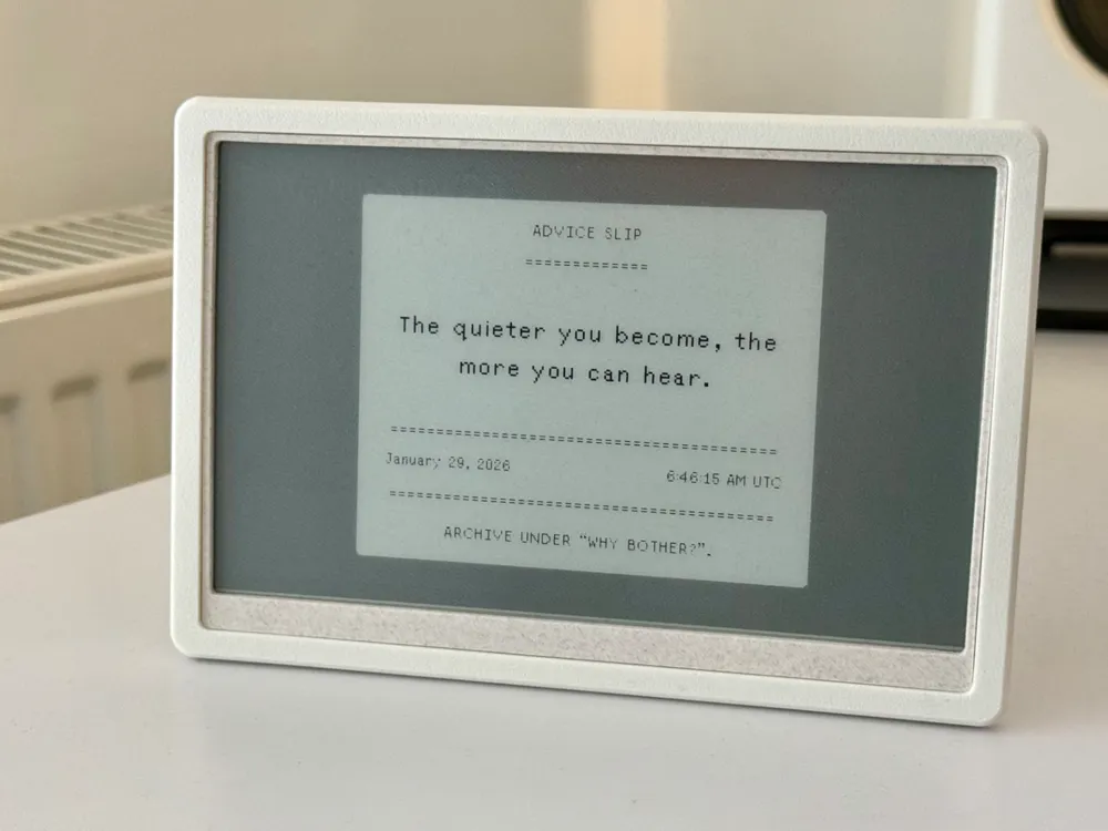
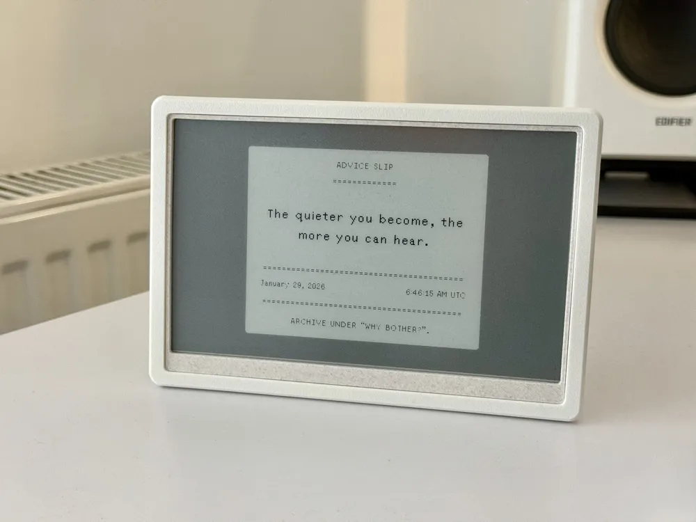
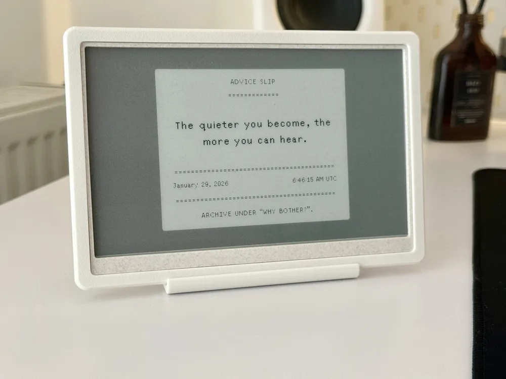
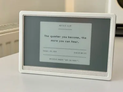
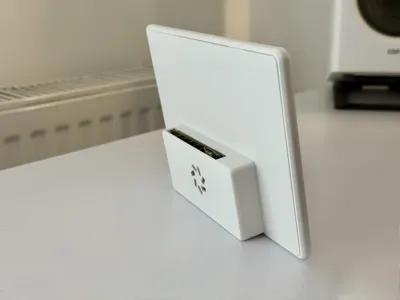
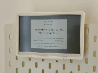
This is a case for TRMNL 7.5" (OG) DIY Kit.
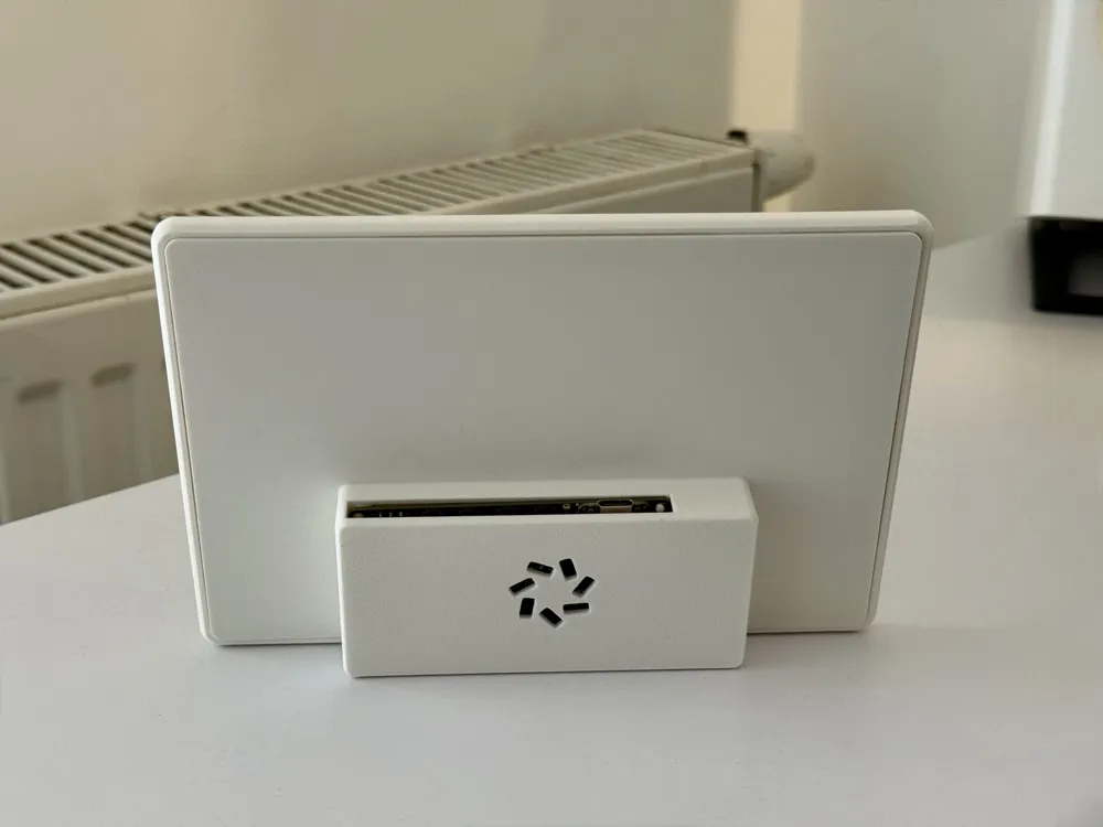
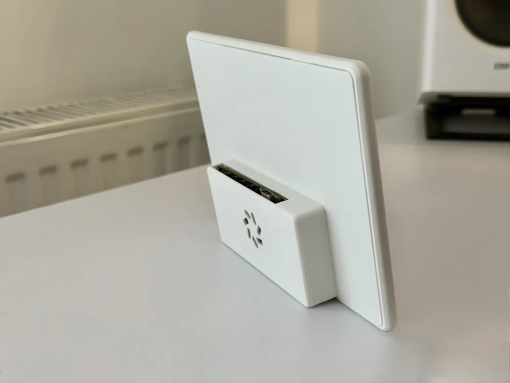
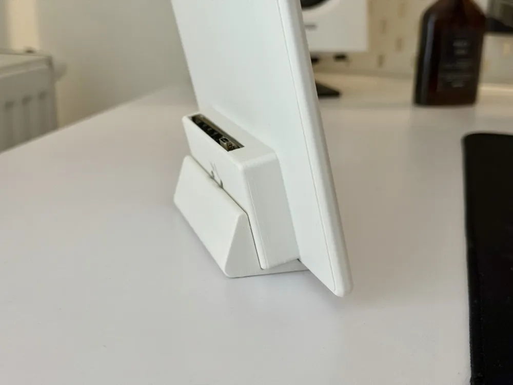
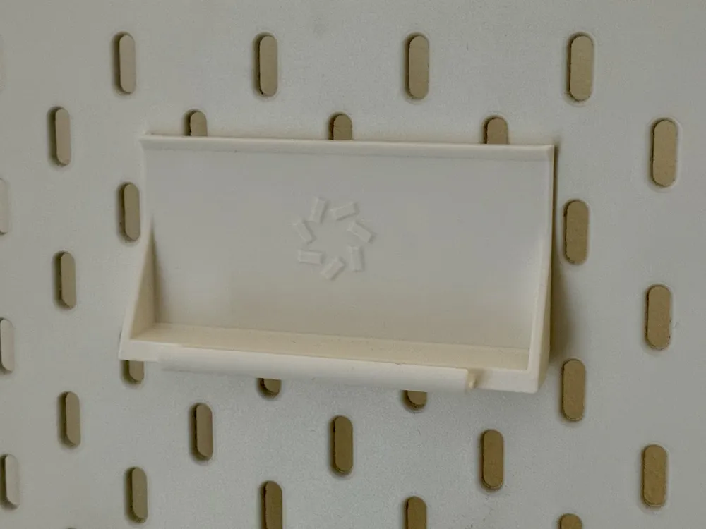
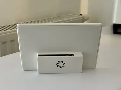
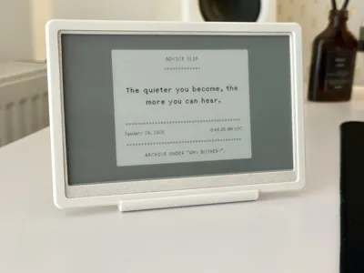
It stands on his own on the desk at a slight angle.
Be aware that it's not the most stable thing ever, you can knock it over due to internals placement but it's not an issue for me.
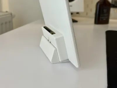
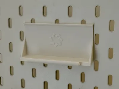
V2 has a desk holder that fixes that.
With this design I wanted to hide the ugly “chin” (bottom) of the display and so I have designed an internal design ring that's slightly inset into the case. In my opinion it looks quite pleasing. Additionally, because it's a separate part you can print it in a different color.
There are two versions (as print profiles):
- V1 - old, requires brass inserts
- V2 - new, improved geometry, stability - no hardware required. Added 3 desk holders - 12.5, 20 and 30 degree tilt.
V2 - new, no hardware required
Everything snaps together.
- Insert the display ring into the front of the enclosure (it only goes one way, there is a lip there)
- Line up the EPD display with the posts inside of the front of the enclosure
- Route the EPD cable through the opening of the midframe
- Snap the midframe in place
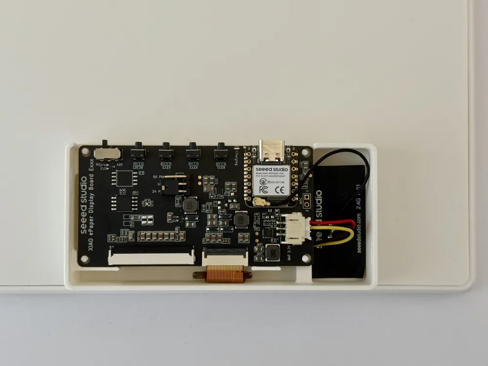
- Put the battery in the holder
- Connect the EPD display to the board, push it into place
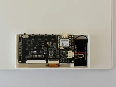
- Route the WiFi antenna to the right
- Connect the battery to the board
- Push in the back of the enclosure.
V1 - requires brass inserts
You will need heat set inserts to mount the PCB
I used M3 heat inserts and M3x8 hex screws - although some of the commenters have said that M2.5 would be better - make sure to check if M3 screws fit through the holes of the board before you melt in the brass inserts.
Before putting it together make sure to snip off the headers on the bottom of the PCB!
They protruded quite a bit in my unit.
PCB sits on top of the battery and you do not want to puncture it.
- Melt the heat inserts (M3 or M2.5) in the midframe
- Put display ring into the front of the case (it only goes one way, there is a lip there)
- Put the eink display into the front of the case (it's quite a snug fit, but I think I managed to get the tolerances right)
- Route the eink display ribbon cable into the midframe (see attached pictures) and push the midframe into the front of the case
- It should snap together, for better fit make sure to push each side of the front of the case inwards
- Put the battery in, route cable as in the pictures
- Put the PCB on top, mount it with screws
- Connect the battery to the board
- Push in the back cover
Printed in Bambu Matte PLA Ivory White + Sunlu Marble PLA Chestnut Brown (display ring).
License

You may create derivative works based on this object, provided that all such derivative works are published exclusively on the MakerWorld platform and include proper attribution to the original creator. You may not share, upload, host, distribute, or publish this object—or any derivative work of this object—on any other digital platform, marketplace, or distribution channel. Commercial use of this object and any derivative works is strictly prohibited. This includes, but is not limited to, selling, renting, sublicensing, or using the object in any context in which you receive monetary compensation or other financial benefits.


Comment & Rating (65)