Parametric Flat Mounting Plate w/ Custom Holes


Print Profile(1)

Description
Updated 2025/10/29 - everything should now work in increments of 0.1 mm
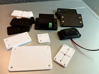
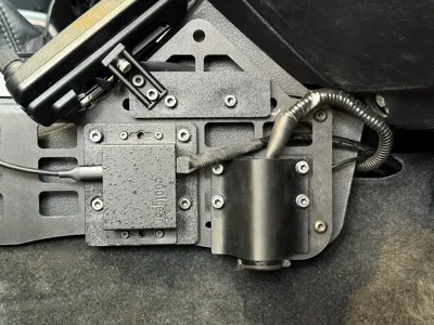
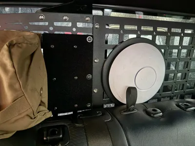
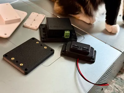
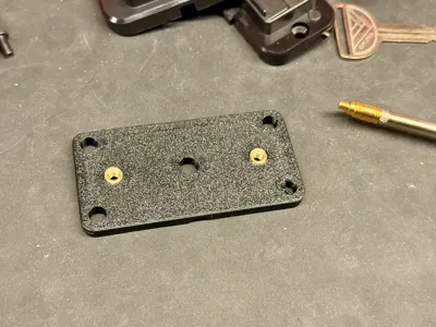
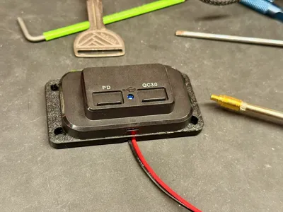
A fully parametric flat mounting plate generator designed in OpenSCAD to create custom bases, covers, or mounting panels for electronics, sensors, and 3D-printed assemblies etc. I used this to create a mounting plate for some USB chargers (as seen in photos) that will be mounted in my truck via zipties/bolts to a molle panel after getting tired of cutting HDPE to size and drilling holes.
This SCAD supports either corner or centre origin coordinate systems (lower-left corner or centre = 0,0) or for hole placement. It supports both CSV-style string input for unlimited holes and individual per-hole entries up to 25.
included 3mf just has a couple random sample plates + the one i used for the USB chargers in the photos.
Key Features
- Selectable origin system - choose "corner" (lower-left = 0,0) or "centre" (plate centre = 0,0).
- Sub Millimeter support - everything should work with increments of 0.1 now.
- Exact W×L×T envelope, even with edge fillets.
- Flexible hole input - string or per-hole text inputs.
- Through-holes, blind holes, and countersinks (45° cone).
- Rounded corners (XY) and optional 3D edge fillets .
- X and/or Y back channels for routing wires or zip-ties.
Back channels are only 1 on either axis as that was all i needed. If anyone needs that to be more configurable let me know and i'll figured out a way to support multiple on each axis.
Notes
- Current version supports one back channel per axis (X and Y).
If you’d like to see support for multiple channels in each direction, leave a comment and i'll add it. - Hole inputs outside the plate bounds will echo a non-fatal warning.
- Edge fillets: set edgeRadius = 0 for faster previews or for sharp edges, then restore for final render.
- Rendering: set fn to a low number when designing, then set to a high number for smooth cures. i usually go above 100 for final export
License
You shall not share, sub-license, sell, rent, host, transfer, or distribute in any way the digital or 3D printed versions of this object, nor any other derivative work of this object in its digital or physical format (including - but not limited to - remixes of this object, and hosting on other digital platforms). The objects may not be used without permission in any way whatsoever in which you charge money, or collect fees.
Comment & Rating (3)