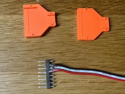
PICKit5 Connector Housing


Print Profile(1)

Description
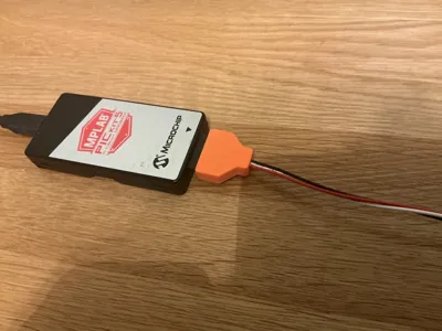
If you are an owner of the PICKit5 programmer to program a huge number of Microchip devices, you know the single in line connector at the edge of the device.
It is fairly easy to create new programming adaptors, but they all look unprofessional since a housing of the “plug” is not available of the shelf.
Here we go: a housing for the 8-Pin connector straight from your 3D printer.
How to use this:
- Create your cable using a single in line DIP row
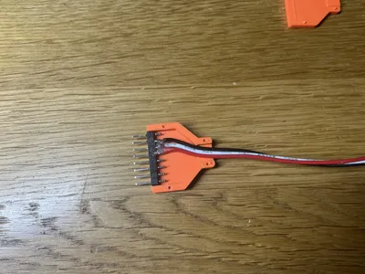
- Glue the connector into the bottom part of the case
- Put some glue at the cable to avoid pulling it to hard
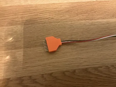
- Glue the case parts finally togeter
Looks almost like a manufactured part.
License
You shall not share, sub-license, sell, rent, host, transfer, or distribute in any way the digital or 3D printed versions of this object, nor any other derivative work of this object in its digital or physical format (including - but not limited to - remixes of this object, and hosting on other digital platforms). The objects may not be used without permission in any way whatsoever in which you charge money, or collect fees.
Comment & Rating (0)