
Star Wars Galactic Empire Inspired Control Panel
Print Profile(1)

Bill of Materials







Description
Thanks for checking out my model! Interested in supporting my work or selling prints?
Support Crew – Show some love and help keep the projects flowing
Galactic Maker Foundry – Sell physical prints of my original designs
Foundry License+ – Sell prints and use my photos for listings
🎉 Supporter-only Discord coming soon – get early access, tips, and sneak peeks!
Membership
Join here to support or get a license
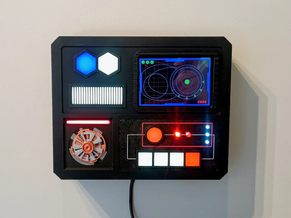

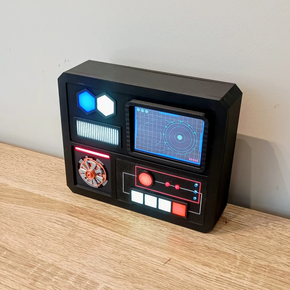
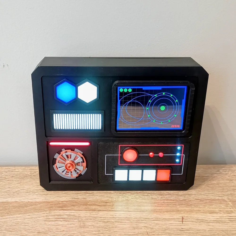
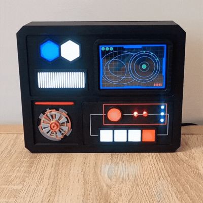
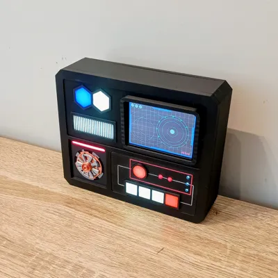
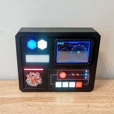
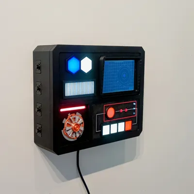
Recovered from a small Imperial outpost on the forest moon of Endor, this panel once tracked inbound starships and pinged their transponders for friend-or-foe identification. This Original Trilogy–inspired Imperial panel recreates that vibe with an Arduino UNO, a 3.5″ TFT running a radar-sweep animation, and LED status lights. All USB-powered—ready for your workshop bulkhead
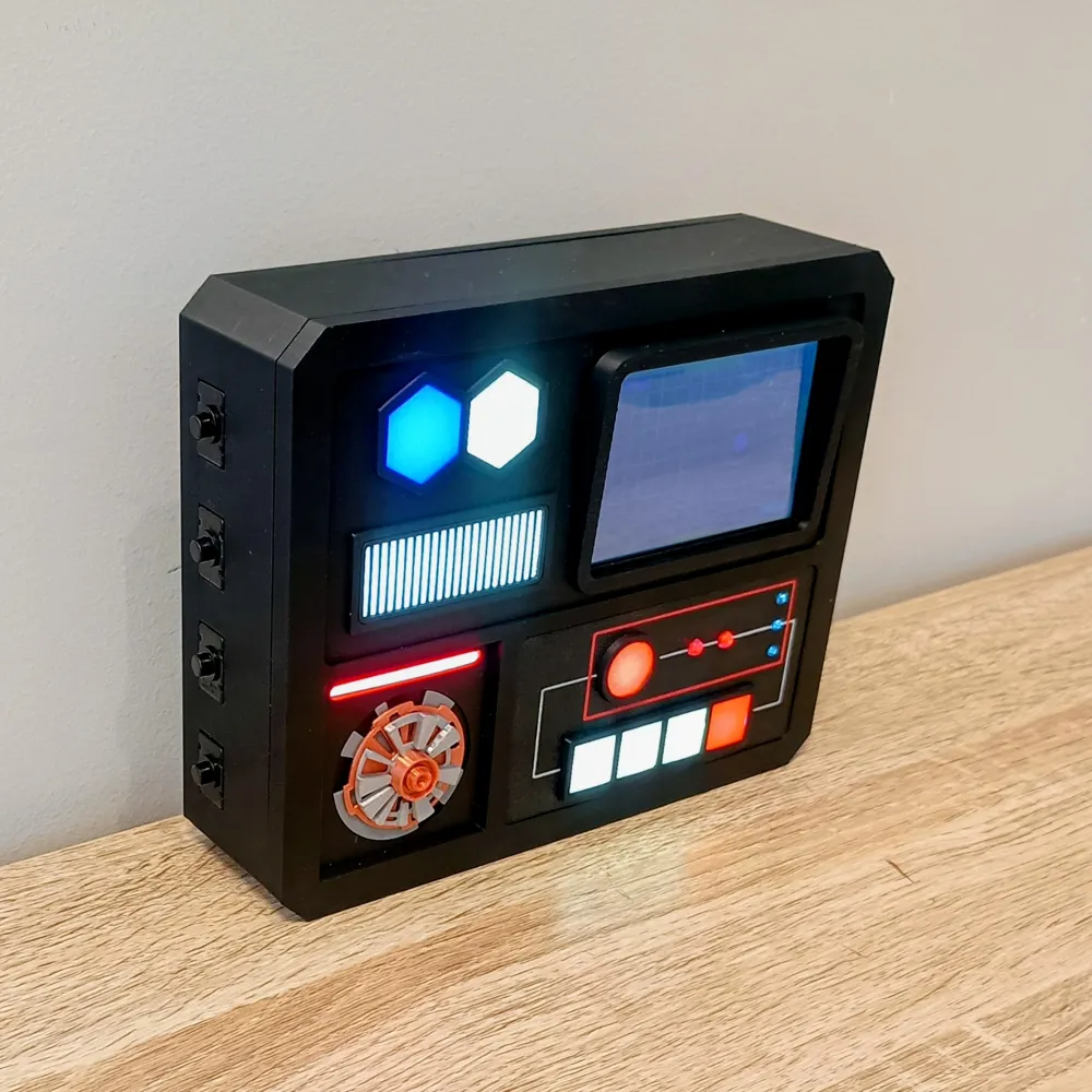
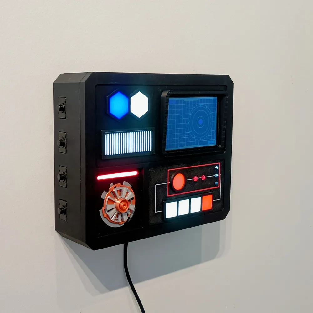
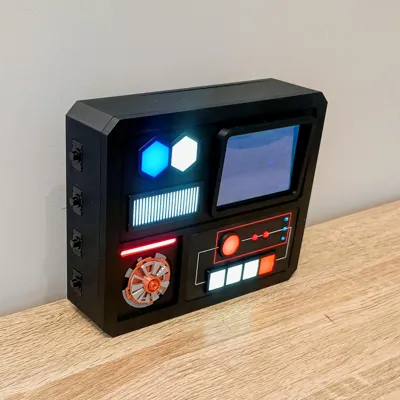
This upload includes two side-panel variants: one with 4 switch cutouts (recommended — the LED meteor changes modes by power-cycling, which is easiest with a switch) and one with no cutouts for a clean look if you prefer always-on wiring. There’s also a power-bank option: the side panel is enlarged to house a bank up to ~155mm × 70mm × 30 mm (please double-check your bank’s dimensions and leave a bit of clearance), and the Power-Bank Insert has a cutout to route the USB cable. The panel can stand upright on a desk, and I’ve included a French cleat that works with Command strips for easy wall mounting.
Files & download:
MakerWorld doesn’t accept .BMP or .INO uploads directly, so I’ve bundled them in a single ZIP. Inside you’ll find PANEL.BMP (the background image) and StarWarsControlPanel.ino (the Arduino sketch). Just unzip and you’re good to go.
Assembly (Quick Start)
- Glue diffusers — Use a few drops of CA/super glue on the inside edges; that’s plenty. Press each diffuser in from the rear until flush. Avoid flooding with glue (it can fog the plastic). Also glue the Lower Right Pattern panel to the front—this piece mimics the Empire’s line schemes on their control panels.
- Glue LED-strip holders — Attach the holders directly behind each diffuser so the LEDs strips surround the openings. A thin bead of CA or a few dabs of hot glue will secure them.
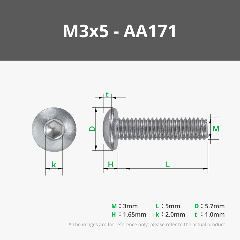
- Droid data port — Push the Droid Back part through the front panel, stack the parts Droid 1 → Droid 2 → Droid 3 → Droid Front, and fasten with M3×5 mm screws. Don’t overtighten.
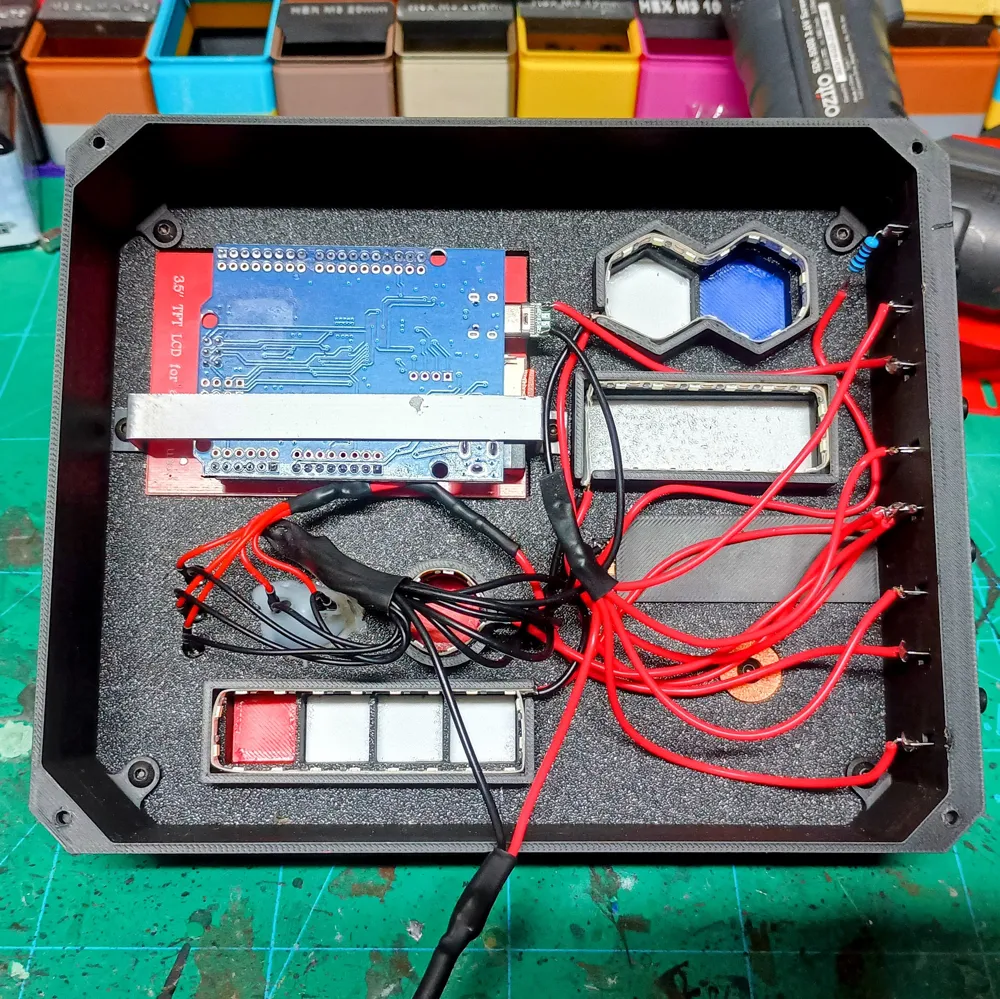
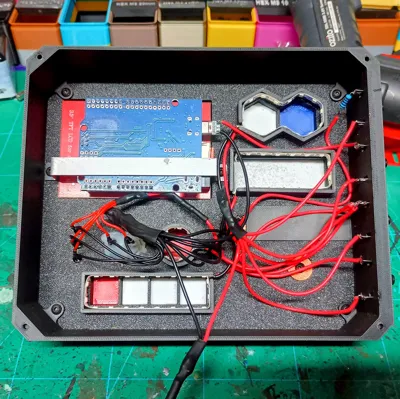
- Cut LED strips — Measure each window and cut the LED strip to fit. For each segment, cut a 20 cm length of red and black wire, strip and tin both the wire ends and the LED strip pads, then solder red to +5 V and black to GND. Stick the strips into the holders.
- Meteor bar — Pre-tin the pads and add wires if needed. Add a 100 Ω resistor inline on the positive lead (cover with heat-shrink), then hot-glue the bar in place with the LEDs facing out and the solder pads to the back. Skip the resistor if your bar already has built-in resistors.
- Discrete LEDs — Fit 2 × 5 mm red and 3 × 3 mm white LEDs into their holes. If you aren’t using pre-wired LEDs, you’ll need to add resistors to prevent them from burning out. I added a 470 Ω resistor on the switch line to dull the brightness a bit, as they were quite bright otherwise.
- Screen & code — Copy the provided BMP image named “PANEL.BMP” to the SD card. Then open the Arduino sketch “StarWarsControlPanel.ino” in the Arduino IDE and upload it to the UNO. Once uploaded, power via USB and confirm the radar-sweep animation runs correctly on the 3.5″ ILI9486 TFT.
- Mount Arduino — Place the UNO into the slot from the rear of the front panel, then attach the printed holder to the front panel with M3×5 mm screws. Ensure the USB port is accessible (mine faces toward the middle).
- Insert switches — Press the switches into the cutouts along the edge of the Side part (top to bottom: Meteor, UNO+Screen, White Strips, LEDs). Skip this step if wiring for always-on lighting.
Wiring (plain-English, “single-lead per switch”)
Legend / what the symbols mean
- “+” / “+5V / positive” = the red power wire from your USB supply (5 volts).
- “–” / “GND / ground / negative” = the black return wire to USB ground.
- On a basic SPST switch there are two pins. For our use:
- Power-side pin = the pin that receives +5V from USB.
- Device-side pin = the pin that sends +5V out to your light/device.
(Electrically the two pins are identical—naming them just keeps things clear.)
Typical micro-USB pigtail colors: red = +5V, black = GND, white/green = data (unused). Always double-check your pigtail.
Switch map (top → bottom):
- Meteor LED bar 2) Arduino + screen 3) White LED strip(s) 4) Discrete LEDs (2× red 5 mm + 3× white 3 mm)
Series resistors for discrete LEDs (at 5 V): ~150 Ω for 5 mm red; ~100 Ω for 3 mm white. Put the resistor on the + lead of each LED. IF the LEDs are too bright then you can add addtional resistors to the group just after the switch, I added 1x 470Ω 0.5 W resistor
A) Prep each group’s positive (+) lead (so only one small wire goes to each switch)
- Meteor bar (+): Solder its + wire to the device-side pin of Switch 1. Heat-shrink.
- Arduino/screen (+): Solder the UNO/screen +5 V feed to the device-side pin of Switch 2. Heat-shrink.
- White strip group (+):
- Strip the + from all strip pieces plus one short “extension” wire.
- Twist them together, tin, and heat-shrink the bundle.
- Solder that single extension to the device-side pin of Switch 3.
- Discrete LED group (+):
- After their resistors, strip the + from the 5 LEDs plus one extension.
- Twist/tin/heat-shrink into one bundle.
- Solder that single extension to the device-side pin of Switch 4.
👉 Now each switch has one neat wire on its device side—much easier than trying to solder multiple wires on one pin.
B) Make one clean +5 V feed to all switches
- Cut four short wires for the power-side pins of the four switches.
- Twist those four wires together + one “master extension” wire, tin, and heat-shrink—this creates a +5 V distribution bundle.
- Solder the master extension to the USB +5 V (red).
- Solder each of the four short wires from the bundle to the power-side pin of Switches 1–4.
C) Tie all grounds (–) together once
- Gather all “–” wires: meteor –, strip –, discrete LED –, UNO GND, and USB GND (black).
- Twist/tin into one ground bus and heat-shrink. (Everything shares the same ground.)
D) Power-up test
- Plug in USB power. Flip the switches one by one: meteor, screen, strips, LEDs. Each group should toggle independently.
Optional (no switches): If you don’t want individual switches, twist the positive (+) leads from the meteor bar, Arduino + screen, white strip bundle, and discrete LED bundle into one +5 V joint and connect that single joint to USB +5 V. Tie all negatives to USB GND. Skip Step B (switch feed) and the “device-side pin” parts of Step A. Everything will power on as soon as USB is plugged in.
(Alt: if you want just one master on/off, run that single +5 V joint through a small inline rocker switch, then to USB +5 V.)
Power notes (important)
- Use a decent 5 V USB wall adapter or power bank.
- All devices share the same USB +5 V (via the switches) and return to the same USB ground; the UNO is powered from USB as well.
Mounting
- Screw on the back panel.
- Wall: use the printed French cleat with two large sized Command strips.
- Desk: it sits flat as is.
Options & Tips
- Power-bank build: use the longer M3×12–20 mm and the extra 6× M3×5 mm to screw Power Bank insert to Back Plate; route USB inside.
- Weathering: sponge silver on edges; light black/brown wash for that lived-in Imperial vibe.
Bill of Materials (BOM)
Documentation (1)
License

You shall not share, sub-license, sell, rent, host, transfer, or distribute in any way the digital or 3D printed versions of this object, nor any other derivative work of this object in its digital or physical format (including - but not limited to - remixes of this object, and hosting on other digital platforms). The objects may not be used without permission in any way whatsoever in which you charge money, or collect fees.


Comment & Rating (13)