
Basstronic's Rem Pod

Print Profile(1)
Description
My contribution to the ghost hunting community with a 3D printer- a Rem Pod.
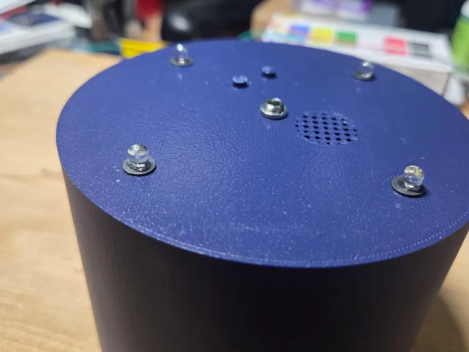
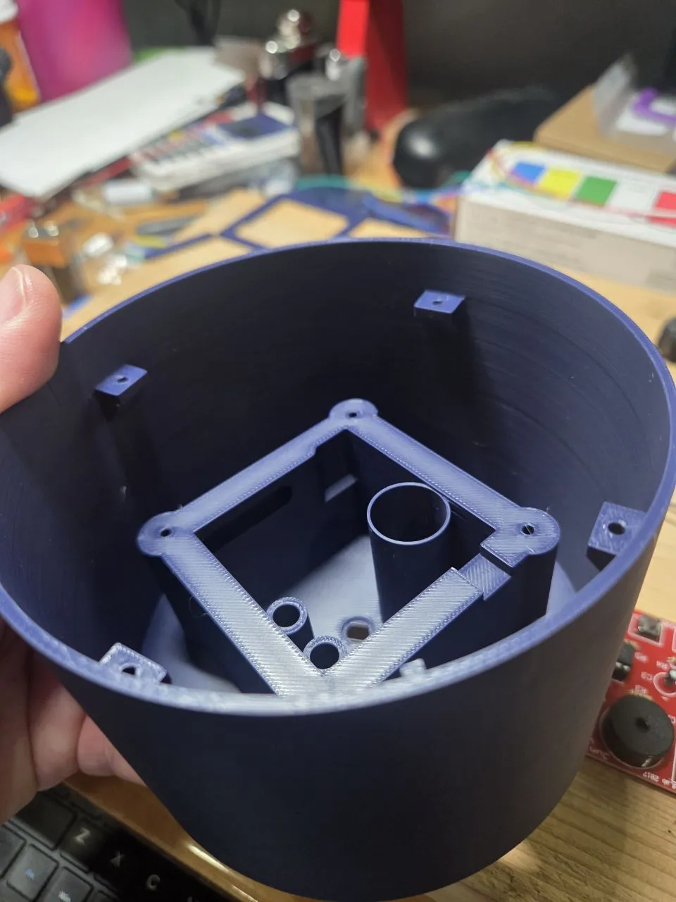
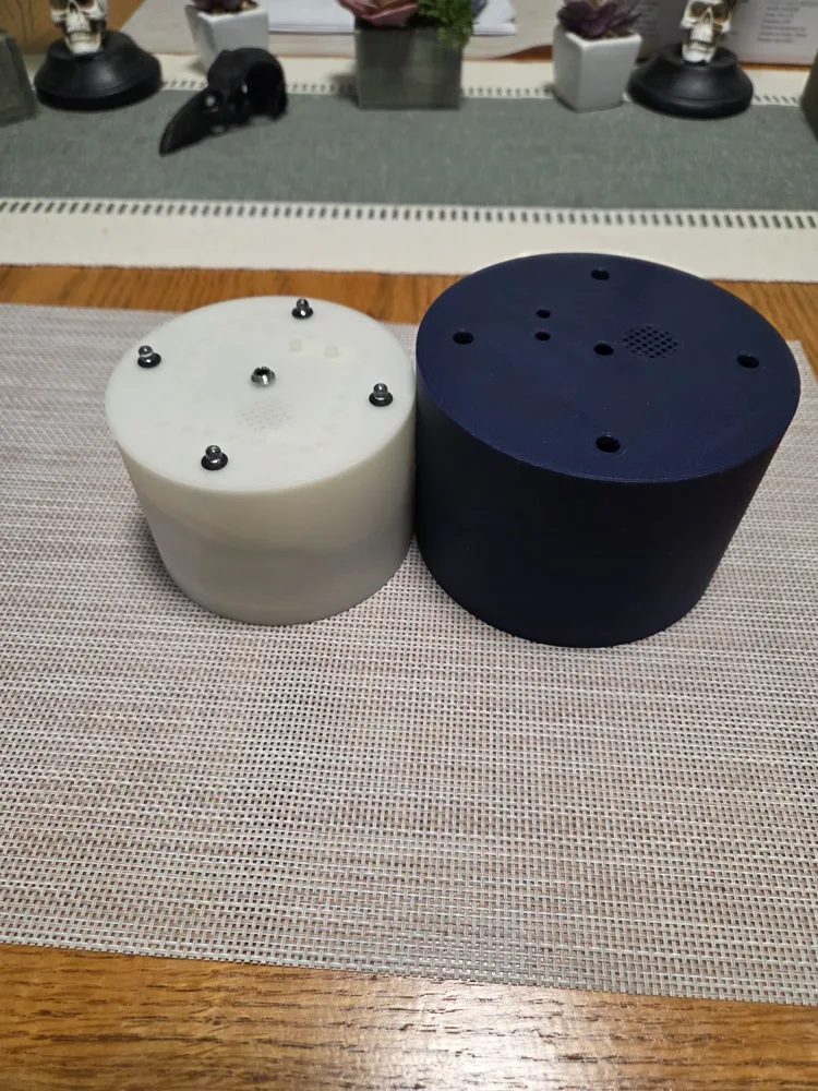
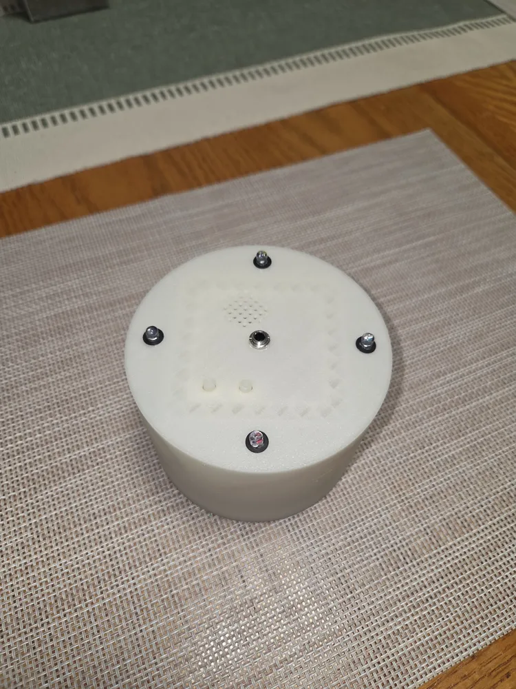
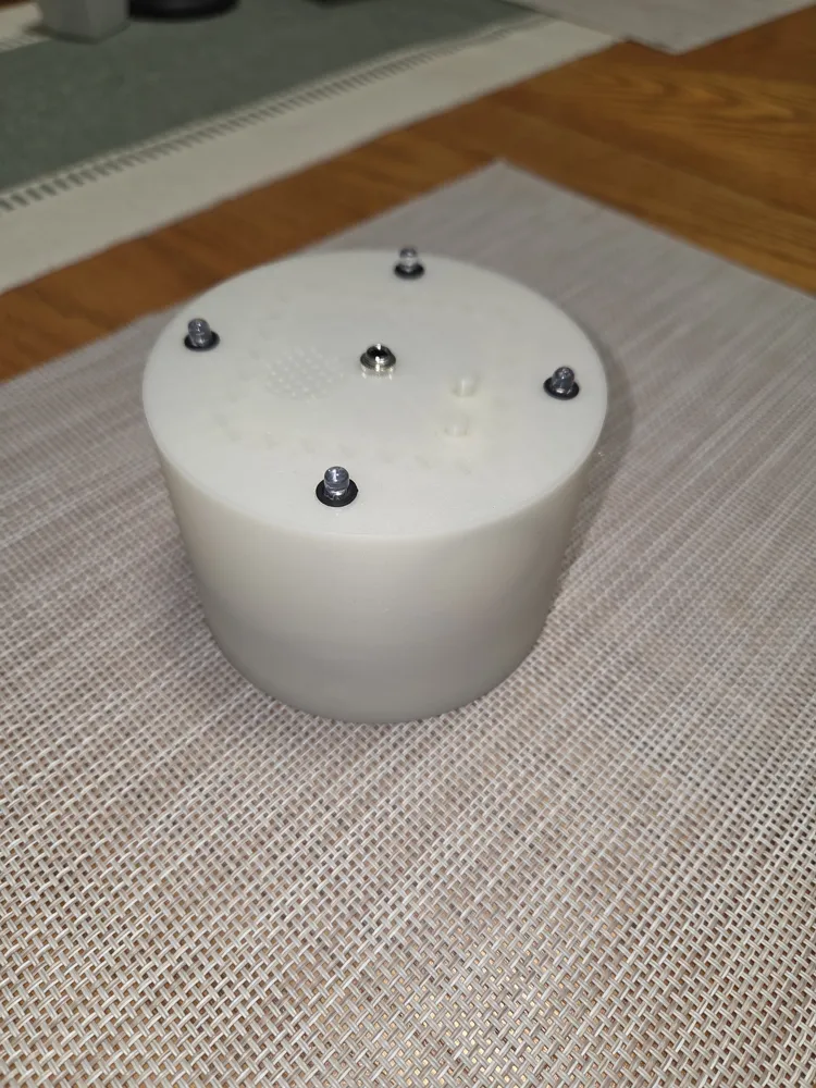
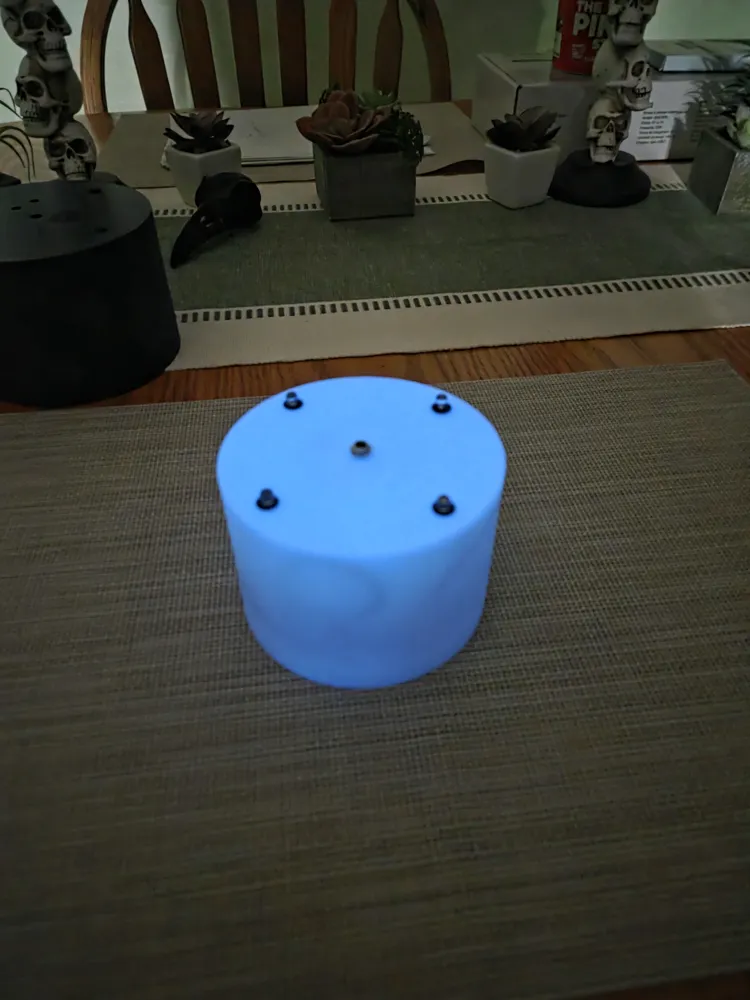
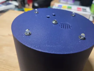
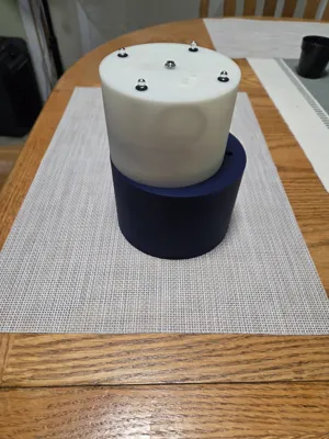
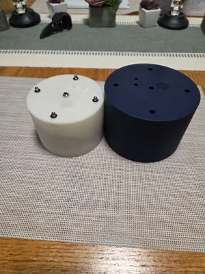
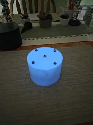
V2 has dropped. The diameter was reduced by 20mm and the height reduced by 12mm. Pictures of the blue are the original, the white is the new. I printed in Glow in the dark blue for the main body and buttons. The bottom, battery bar and board cap I used a natural PLA (clearish).
I didnt want to spend around $200 USD on the official “Rem Pod” or the others in the $120-180 range so here it is. I wanted a design that did not involve hot glue gun or using other fillers such as epoxy. I wanted something fairly clean, solid and engineered. I also wanted something with easy to get parts from Amazon. Knowing I want at least 4 of these devices for our gear stockpile, making them was a cheap and easy option.
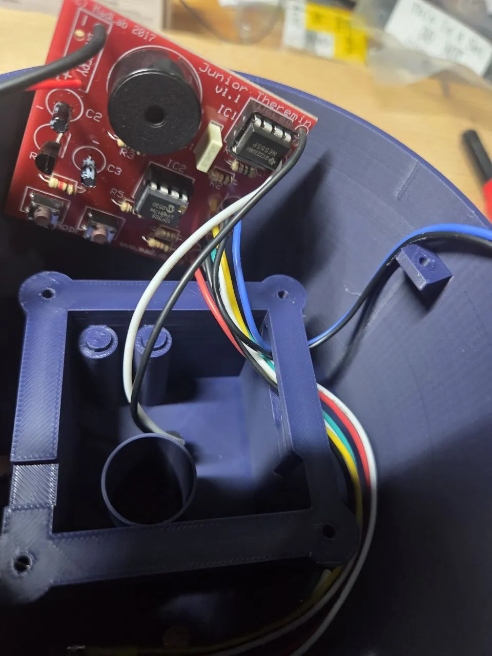
Beware you will need a good soldering iron with a small tip and KNOW how to solder. The JR Theremin is in kit form and is designed for novice circuit soldering folks. Just get a good soldering iron and do not be crazy on the heat- 300c did it for me no issues.
#4x1/2" LG pan head sheet metal screws from local hardware store
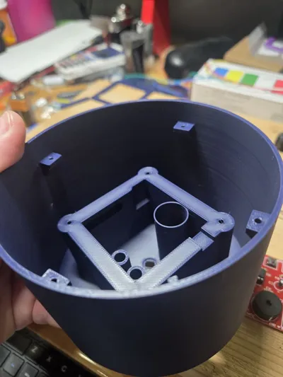
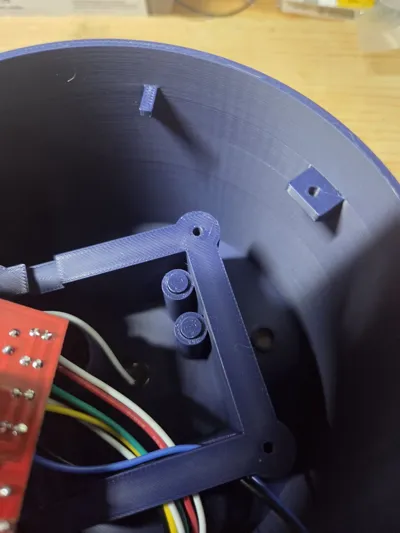
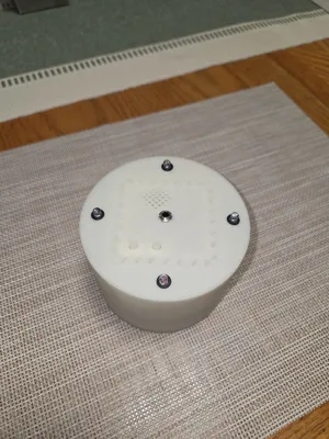
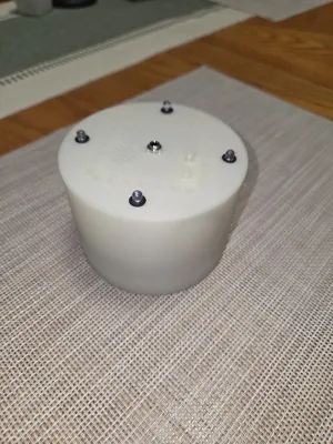
The assembly is comprised of a Rem Pod body, 2 buttons, board cap, bottom and battery bar.
Assembly:
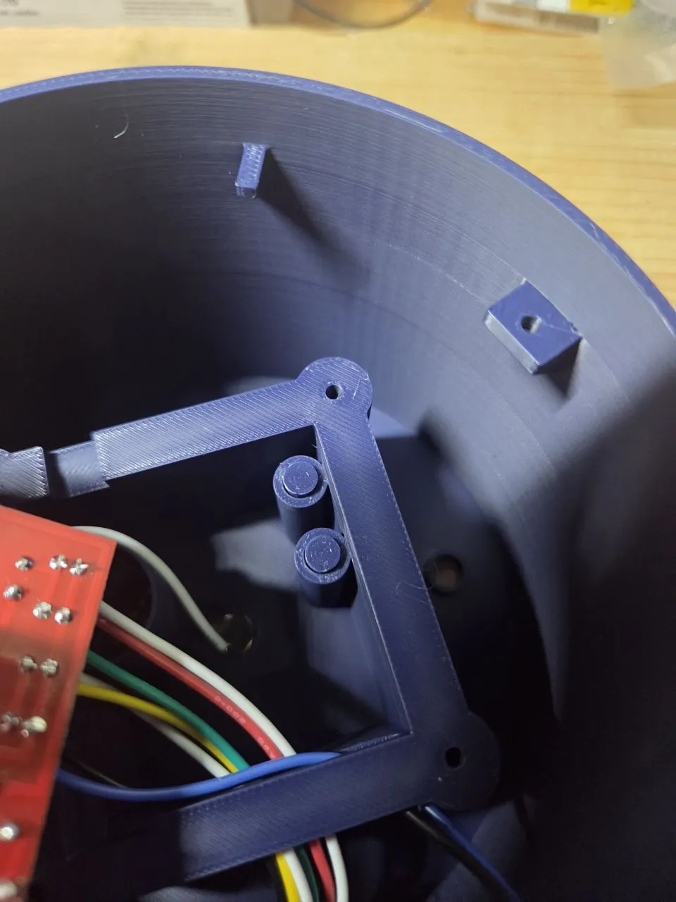
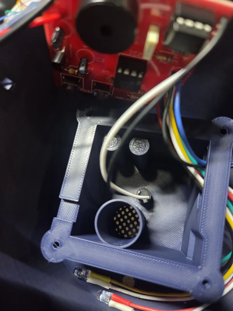
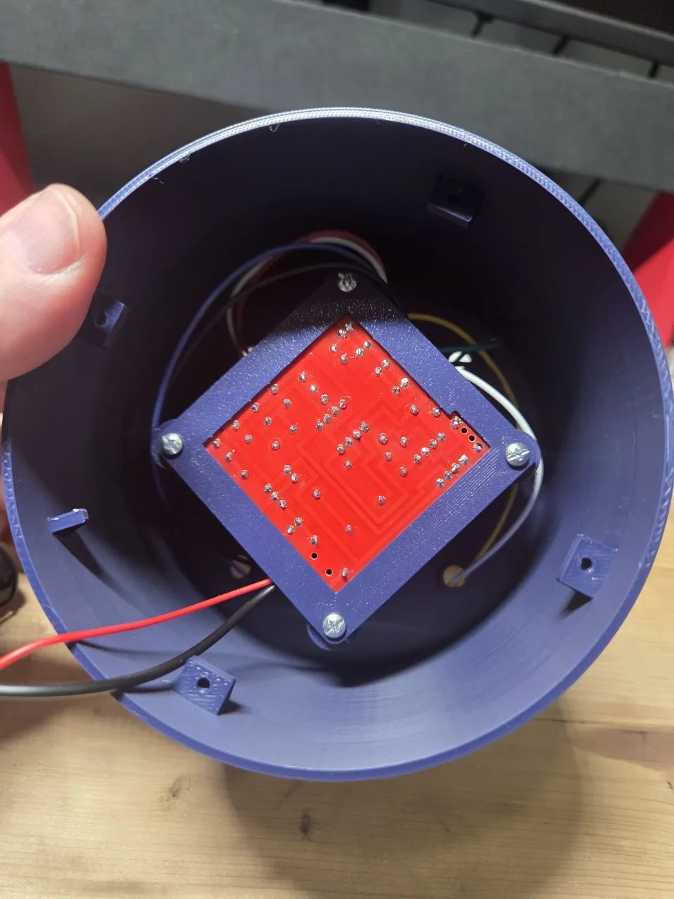
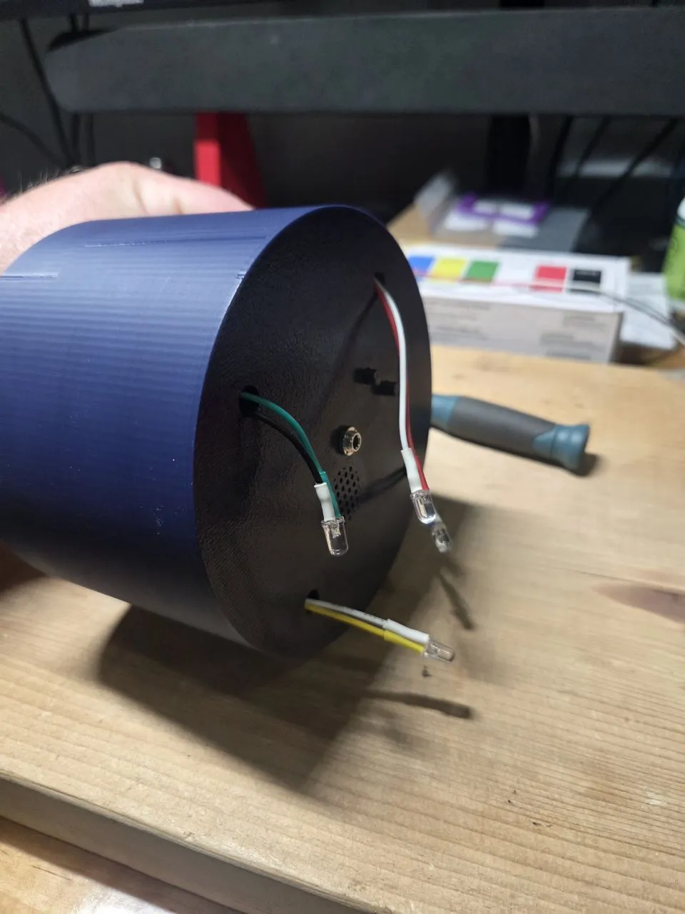
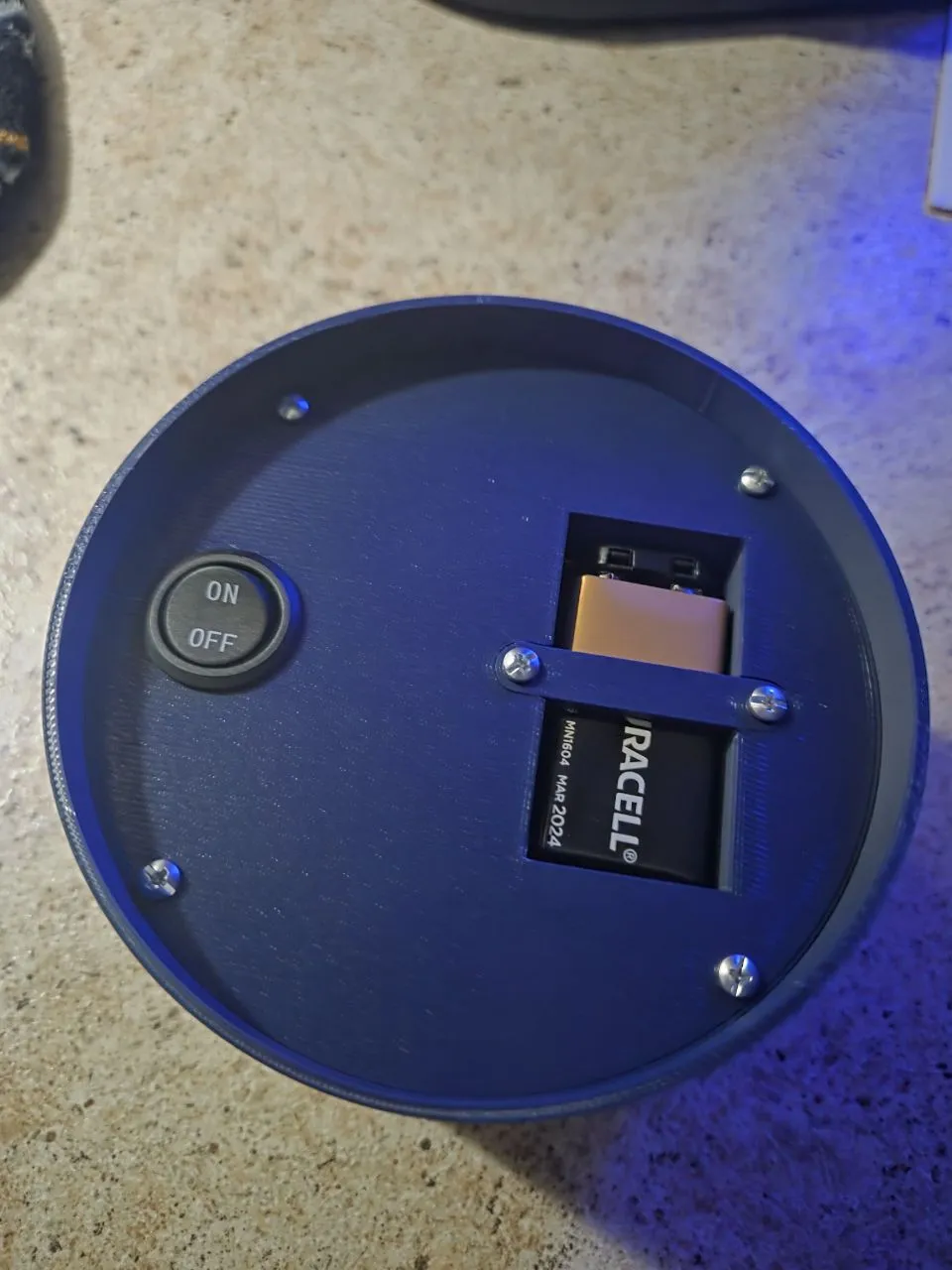
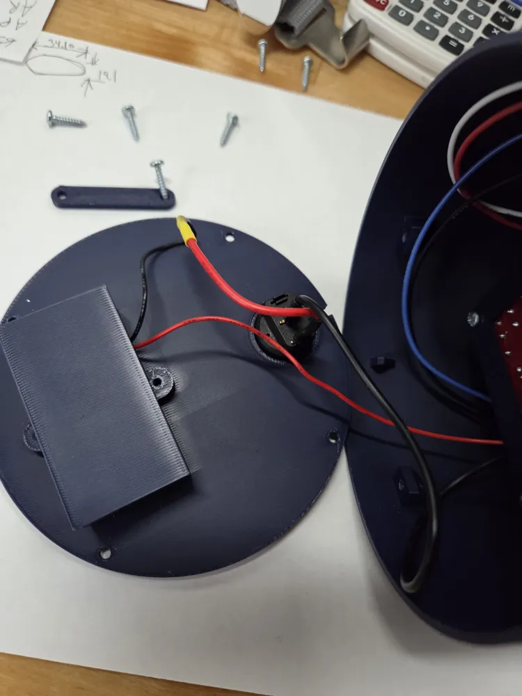
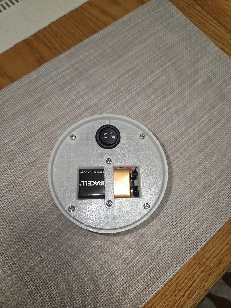
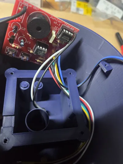
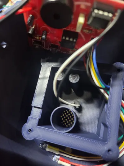
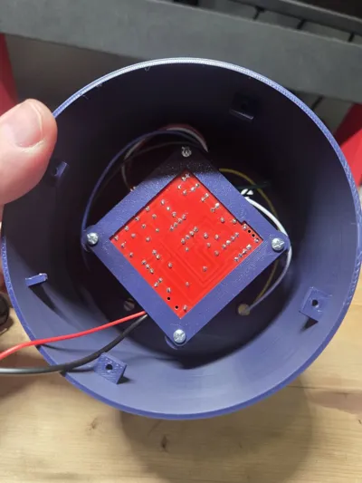
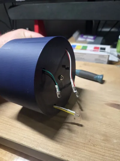
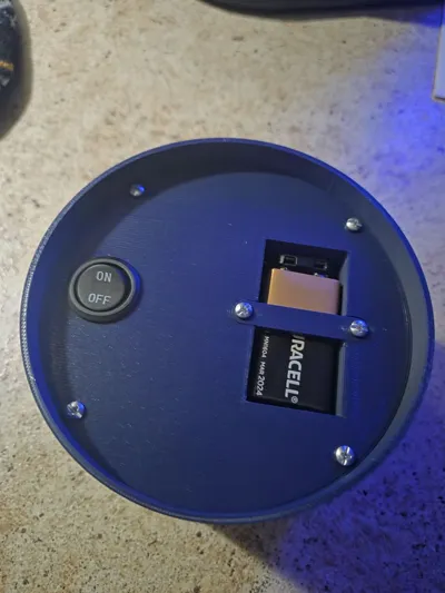
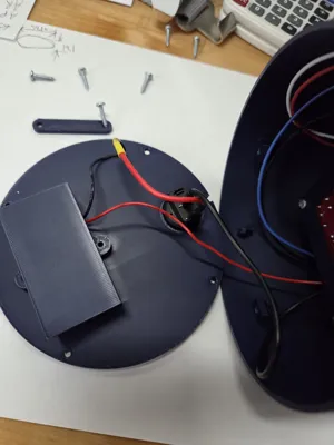
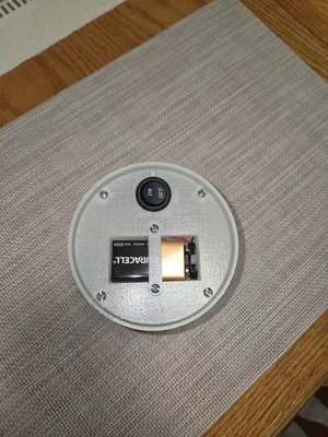
Solder up the JR Theremin, assemble it. For LED's wire per the attached photos. Gage your wire lengths depended on where the board sits, the LED slot and what hole they will pop out of. My longest LED wire is approx 6" in the photo and I was a bit generous. The antenna connection I used the Neutral tab of the jack and one others and took each wire separate to the board. Place the two printed buttons into the housing. *UPDATE*The 9V batter circuit is fairly straight forward. Wire the positive to positive and negative to negative. To wire in the switch you must cut it into one of the legs, I cut the negative and wired it right in line. Route the LED wires thru the LED slot and just pull them to the side for now. Place the antenna jack in the center hole and affix to top side with nut. Place board face down aligned with the piezo chamber, place board cap on back side affix with (4) screws- note the Power wires need to run out the slot allowed for them. Now route the LEDs thru each hole, pull completely thru. Place an LED holder on it and reinsert down into the hole (LED should stick out and not just push thru the holder). Flip the unit bottoms up, slide the wires thru the switches slot and place switch into hole. Pull the 9V connector thru the battery slot into the battery chamber. Place bottom into Rem Body noting its keyed location, secore with (4) screws. Attach 9V battery, place into chamber. Place battery bar over it and secure with (2) screws.
Happy Ghost Hunting!
License

You shall not share, sub-license, sell, rent, host, transfer, or distribute in any way the digital or 3D printed versions of this object, nor any other derivative work of this object in its digital or physical format (including - but not limited to - remixes of this object, and hosting on other digital platforms). The objects may not be used without permission in any way whatsoever in which you charge money, or collect fees.


Comment & Rating (10)