
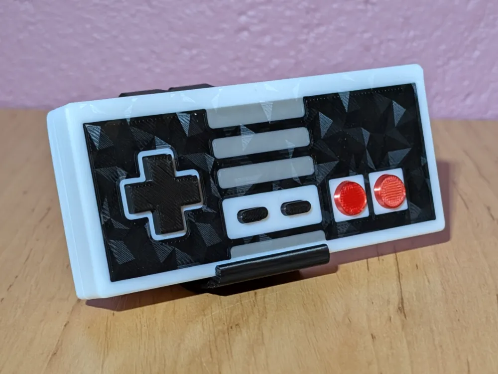
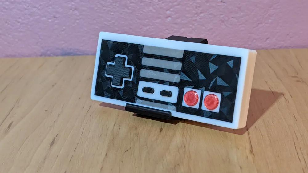
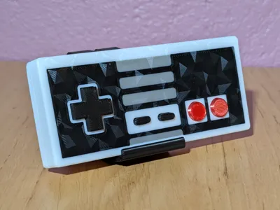
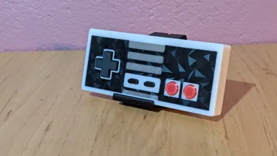
Fully functional NES-Controller for PC with USB-C
Print Profile(2)


Bill of Materials





- G90 6x6x5mm tactile switches x 8:
- 3m USB-C cable x 1:
- Seeed Studio XIAO RP2040 x 1:
Description
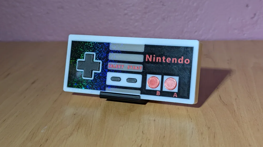
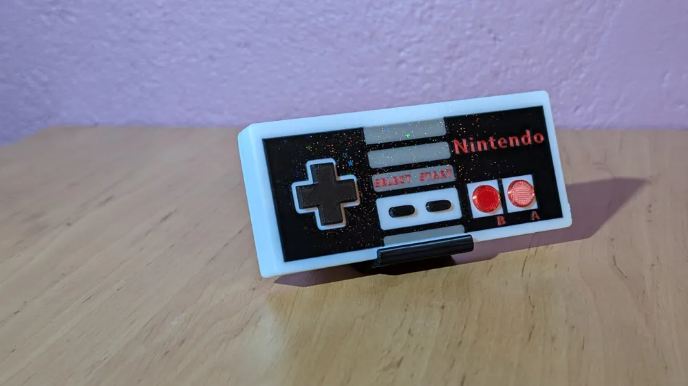
Hi, i wanted to share you my little creation. It`s a litle game-controller in the shape of an old Nintendo Entertainment System-controller. You can use this controller on your computer to play some old retro games.
Lets start with the parts you need:
- 1x Seeed Studio XIAO RP2040 https://www.seeedstudio.com/XIAO-RP2040-v1-0-p-5026.html
- 1x USB-Type-C cable 3 metres (or other length like you want)
- 8x G90 6x6x5mm tactile switches
- 1x custom PCB (Gerber files are attached)
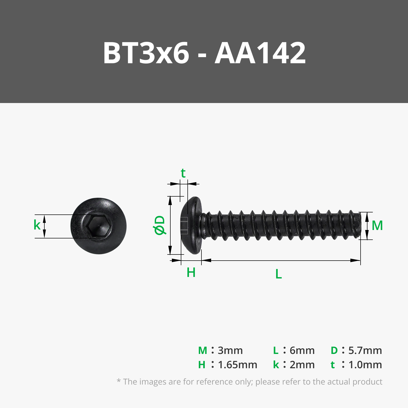
- 2x Bambulab BT3x6-AA142 screws
- 5x Bambulab BT3x10-AA222 screws
- some cables to connect the pcb with the controller
Printing:
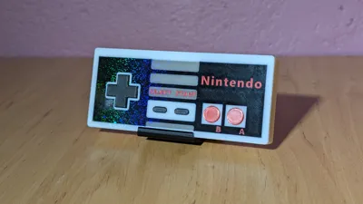
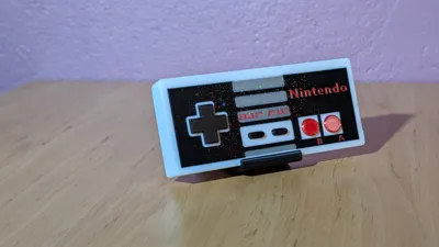
You can print the parts using different building plates in your desired style. Please make sure to use clean building plates to minimize printing errors, especially when printing the version with the logo. For the version with the logo, you should use a 0.2 mm nozzle.
Assembly:
| 1. Install the microcontroller in the housing and secure it with a BT3x6 screw and the 3D-printed holder. | 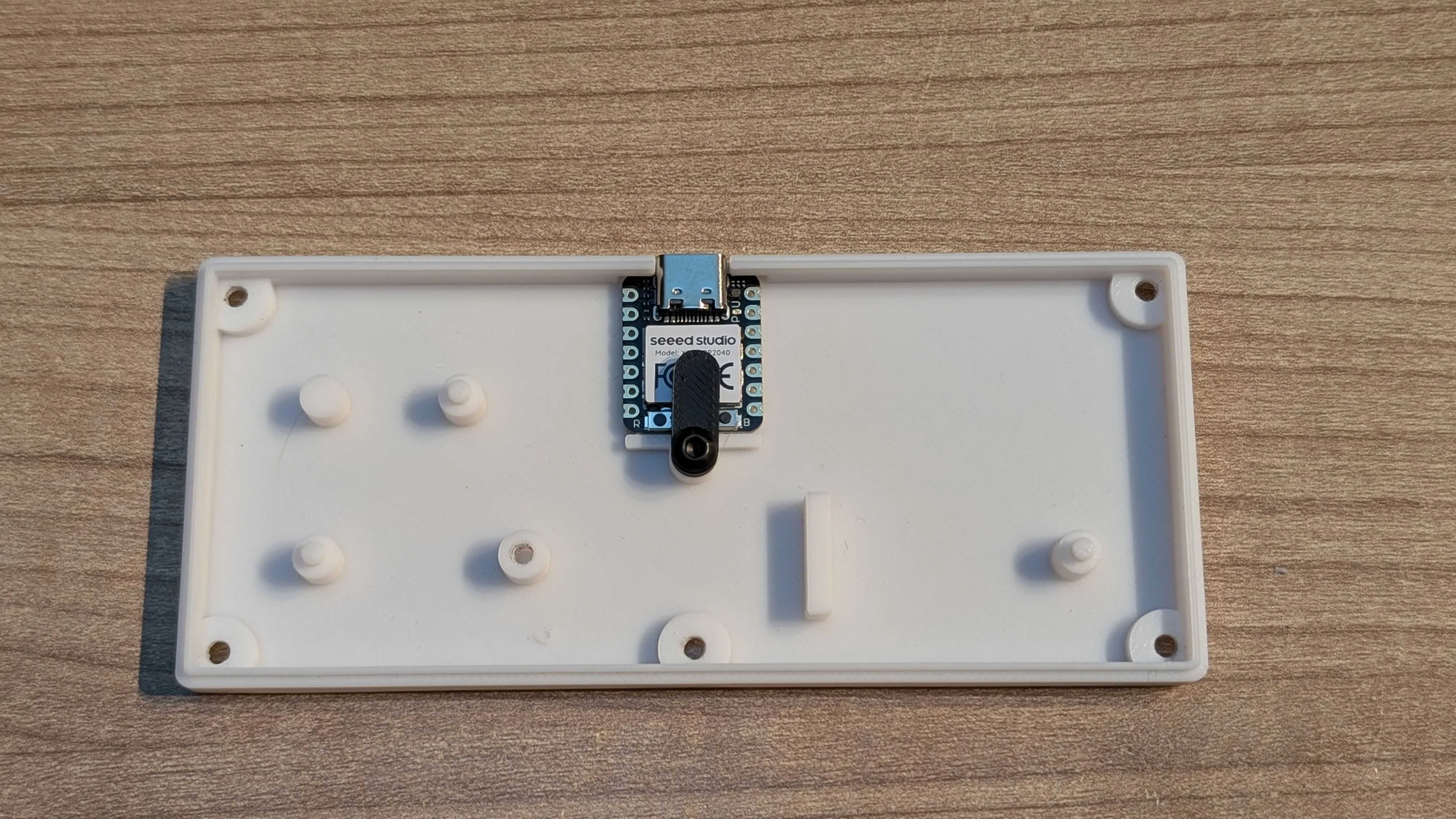 |
| 2. Place the buttons on the PCB and place the assembly in the soldering aid. | 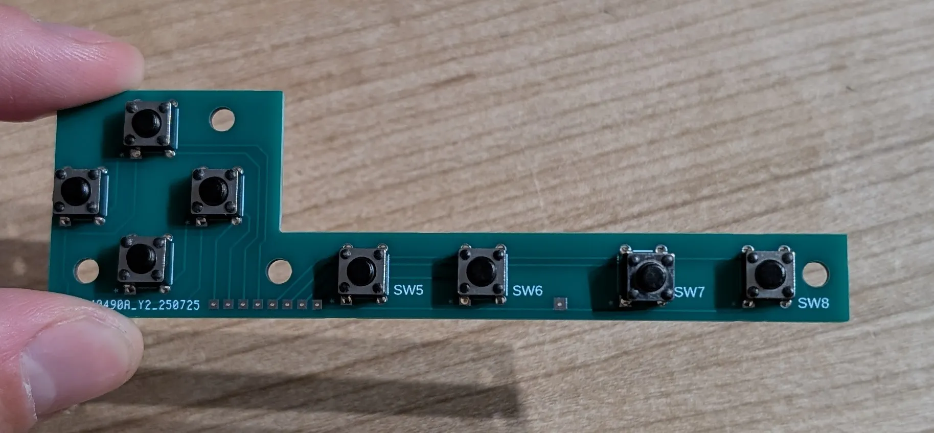 |
| 3. Place the assembly in the soldering aid and solder all buttons. | 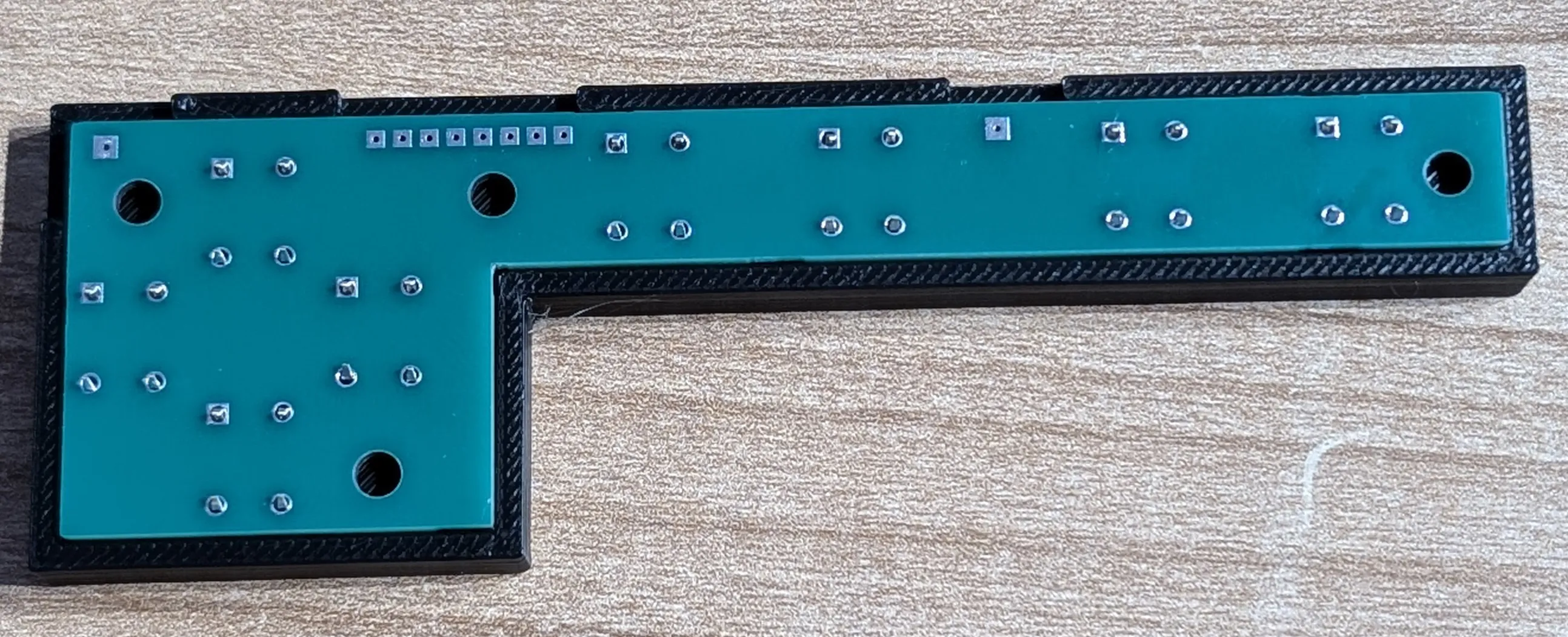 |
| 4. You can now place the finished PCB in the case to solder the cables. | 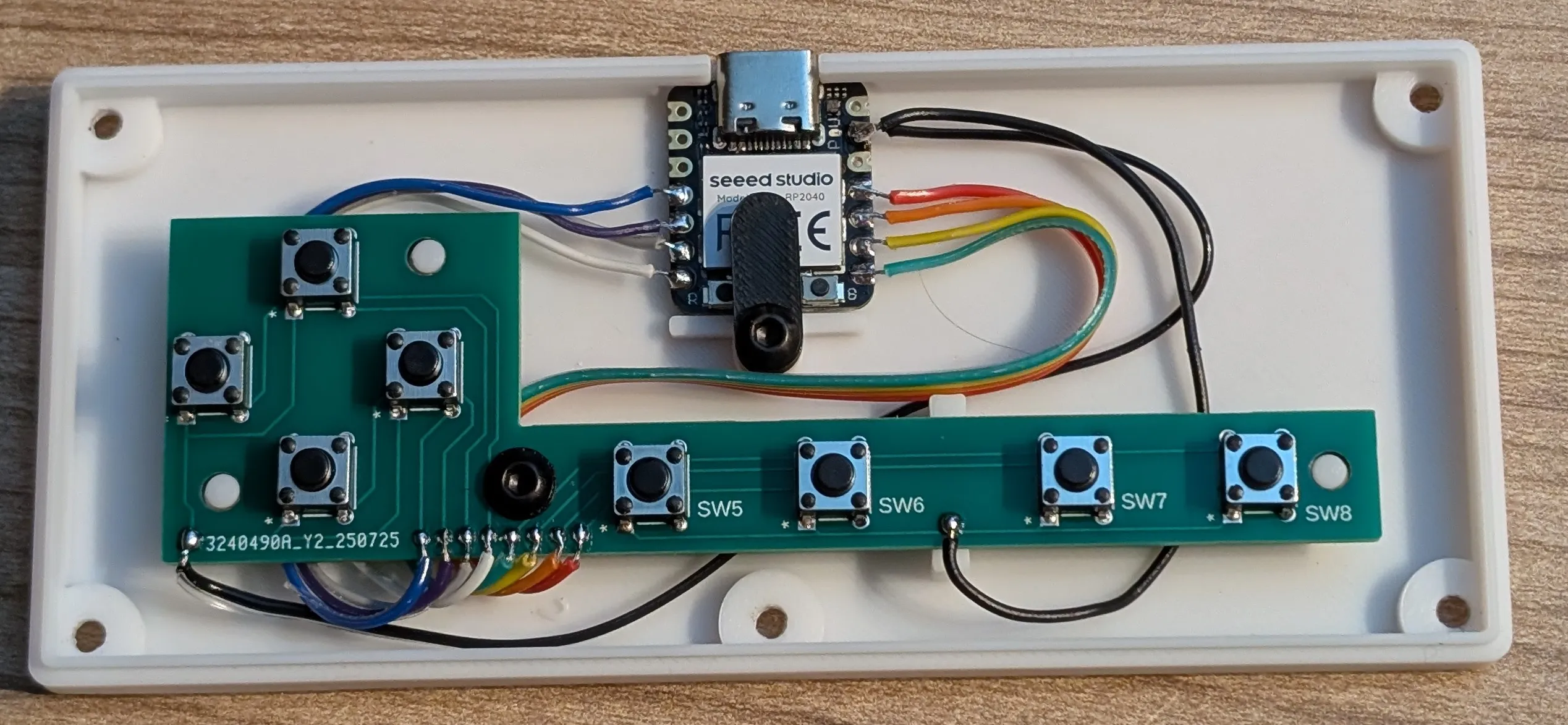 |
| 5. Let's start by soldering the two GND cables. A 14 cm long cable is required for buttons 1-4 (control pad). A 9 cm long cable is required for buttons 5-8 (Start, Select, A, B). Both cables are then soldered to the GND connection of the controller. | 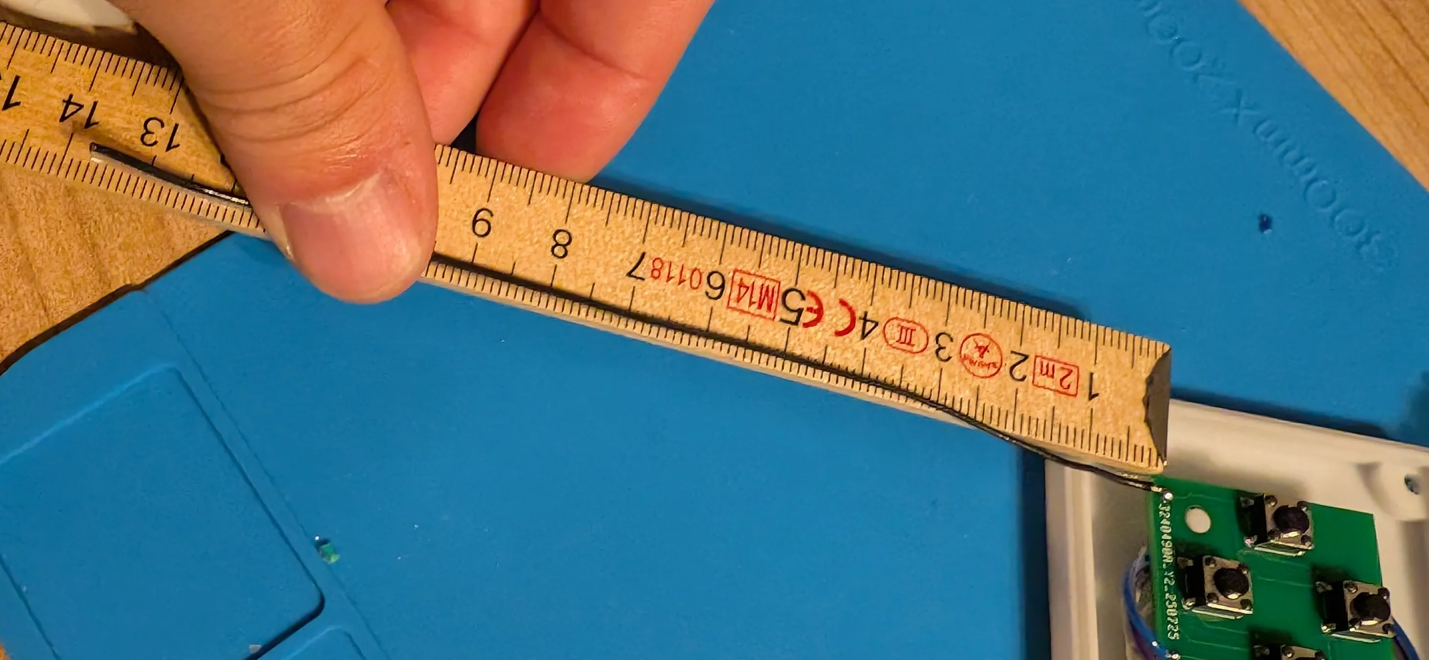 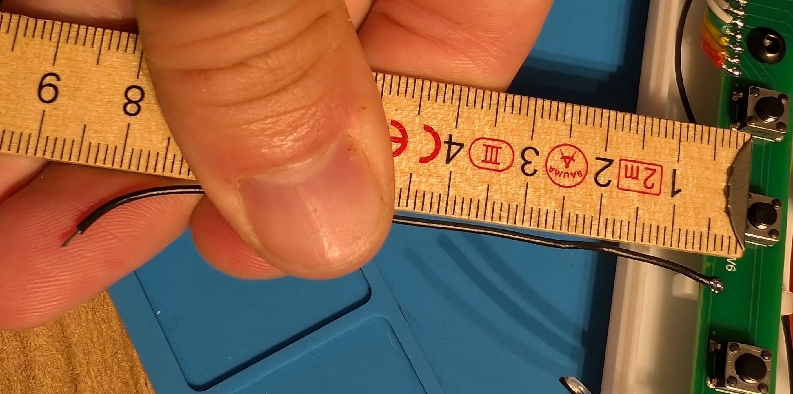
|
| 6. Next, we will solder the cables for buttons 1-4. Let's start at the PCB on the left solder pad. Solder pad 1 is connected to D3 of the controller. Solder pad 2 is connected to D4, solder pad 3 to D5, and solder pad 4 to D6. I recommend a cable length of 8 cm. | 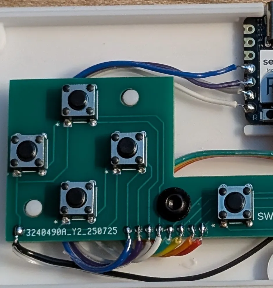 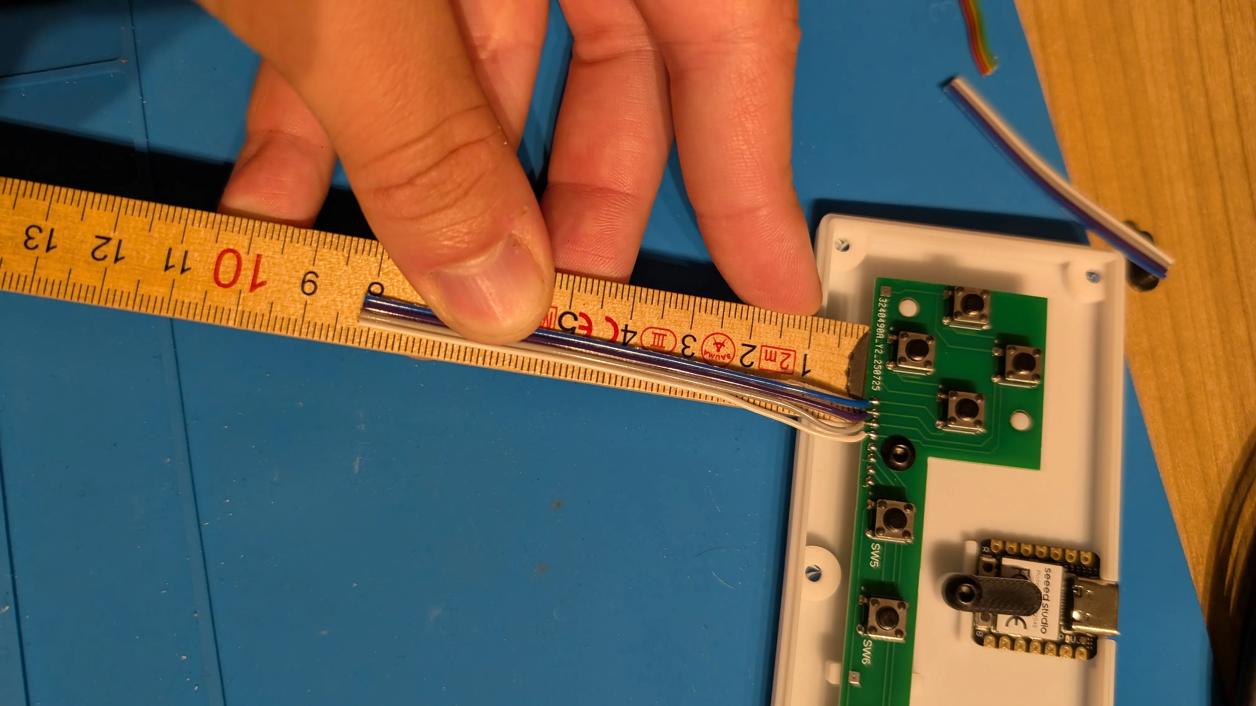 |
| 7. Next, we will solder the cables for buttons 5-8. We will proceed from left to right again. Solder pad 5 is connected to D7 of the controller. Solder pad 6 is connected to D8, solder pad 7 to D9, and solder pad 8 to D10. I recommend a cable length of 11 cm. | 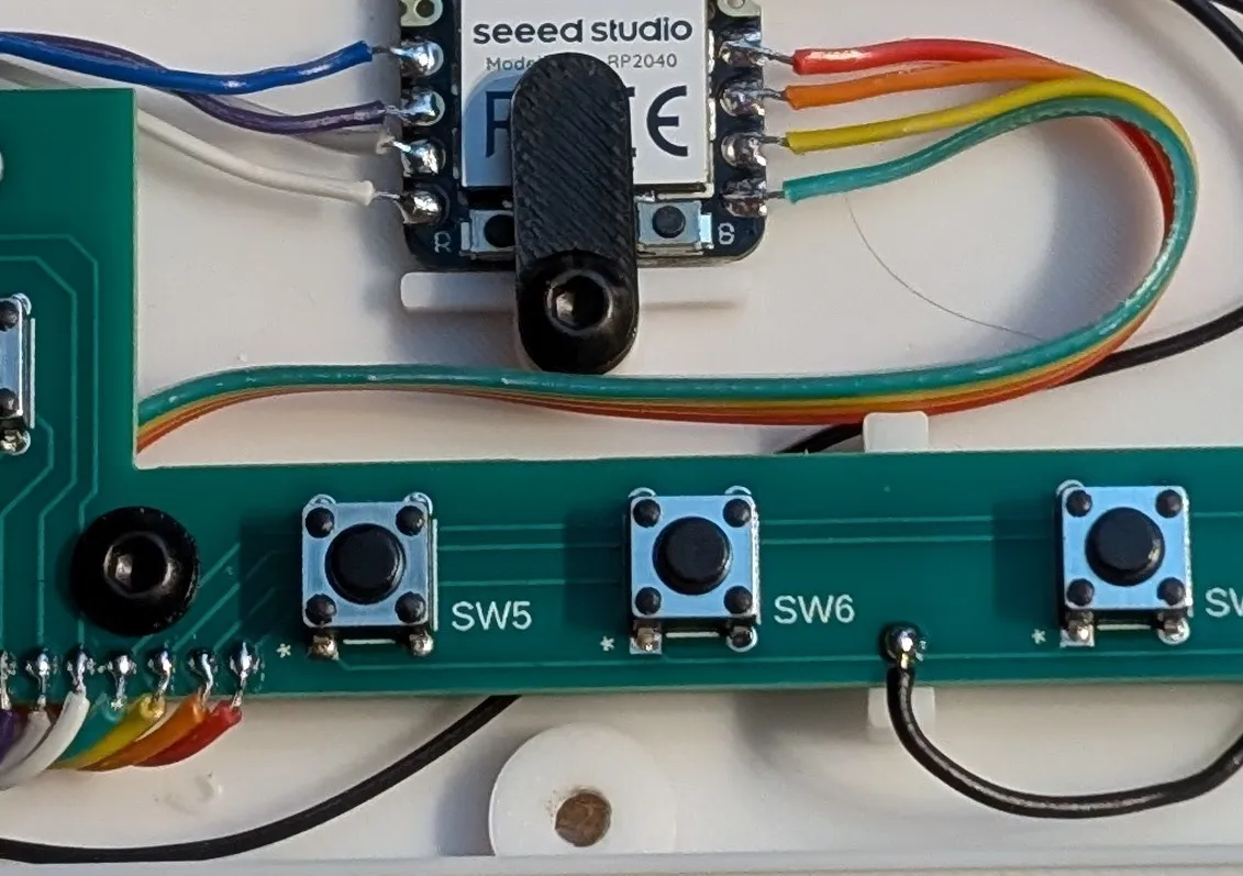 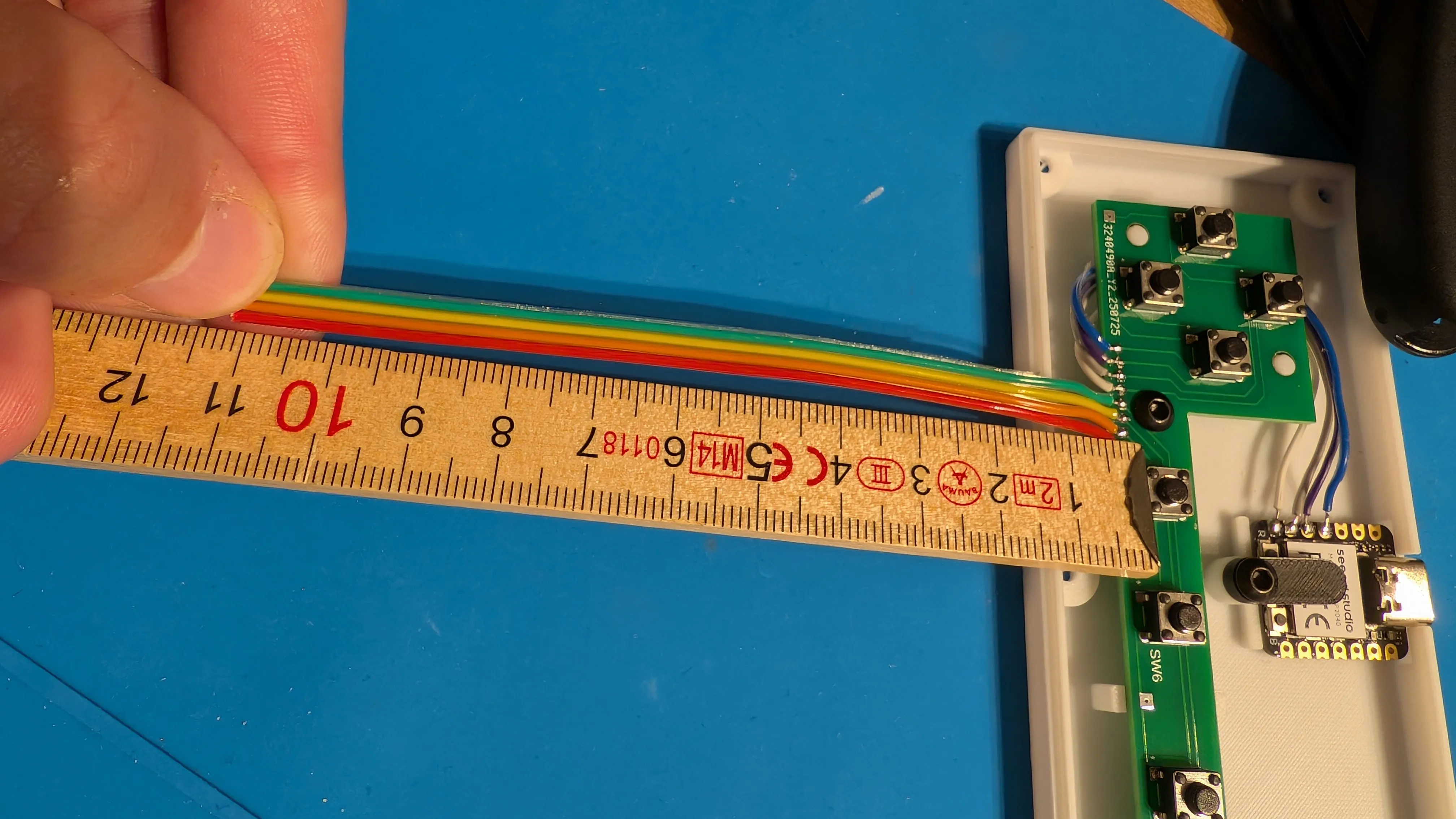 |
| 8. Then screw the PCB to the housing. Make sure to use the printed washer to prevent the screw from scratching the PCB. Use the BT3x6 screw to secure the circuit board. | 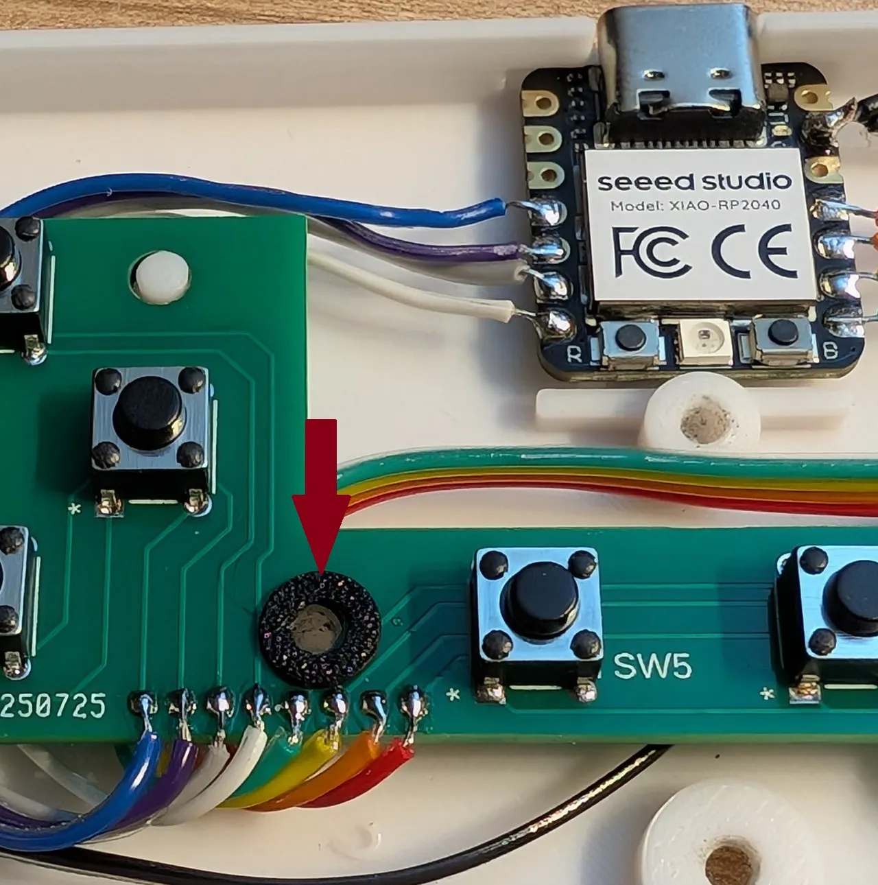 |
Before we close the case, we must first install the software in the next step. | |
Installing CircuittPython firmware:
- Download the appropriate CircuitPython firmware from the official website: https://circuitpython.org/board/seeeduino_xiao_rp2040/
- Connect the XIAO RP2040 to your PC via USB.
- Press the “Boot” button while connecting the RP2040 to your computer.
- The board will appear as a USB drive named “RPI-RP2.”
- Copy the downloaded .uf2 file to the “RPI-RP2” drive.
- After copying, the board will restart and appear as “CIRCUITPY”.
Add libraries:
- Download the CircuitPython library package: https://circuitpython.org/libraries
- Unzip the ZIP file on your PC.
- Copy the “adafruit_hid” folder from the unzipped package to the “lib” folder on the ‘CIRCUITPY’ drive.
- If the “lib” folder does not already exist, create it.
Upload code.py:
- Download the “code.py” file on makerworld and upload it to the “CIRCUITPY” drive.
- You can also find the Code at the end of the description.
If you want to do some changes i can recommend using the “MuEditor”:
- Download the “Mu Editor.” This is best suited for creating code with CircuitPY. https://codewith.mu/
- Start the editor and select “CircuitPython” mode.
- Click on “Load,” then navigate to the ‘CIRCUITPY’ drive and load the “code.py” file. If this file is not yet available on the drive, create the file.
Final assembly:
Once everything has been soldered and the firmware and code have been uploaded, we can close the case.
| 1. Place the printed buttons in the top of the housing. | 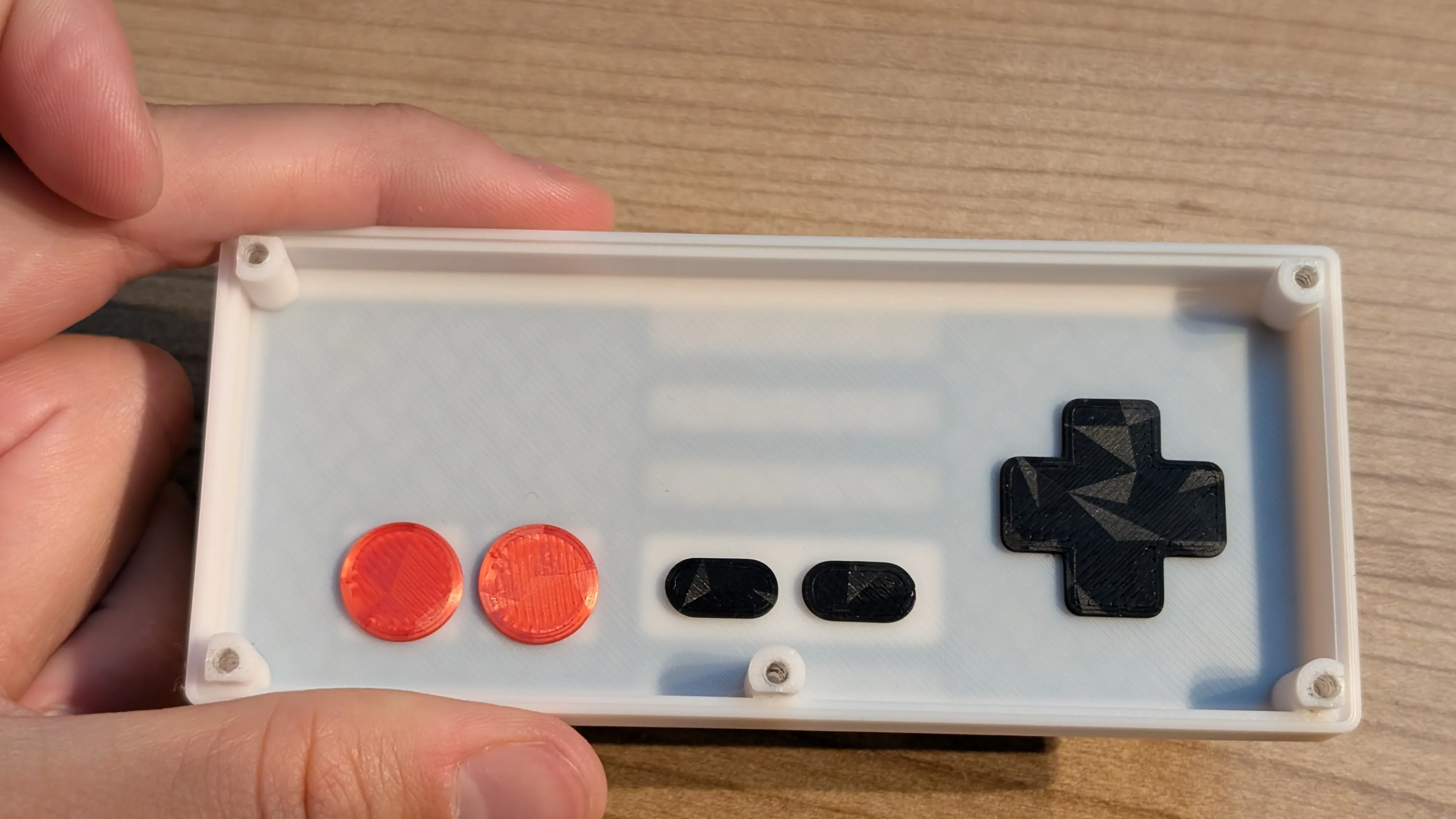 |
| 2. Place the two halves on top of each other and screw them together at the back using 5x BT3x10 screws. | 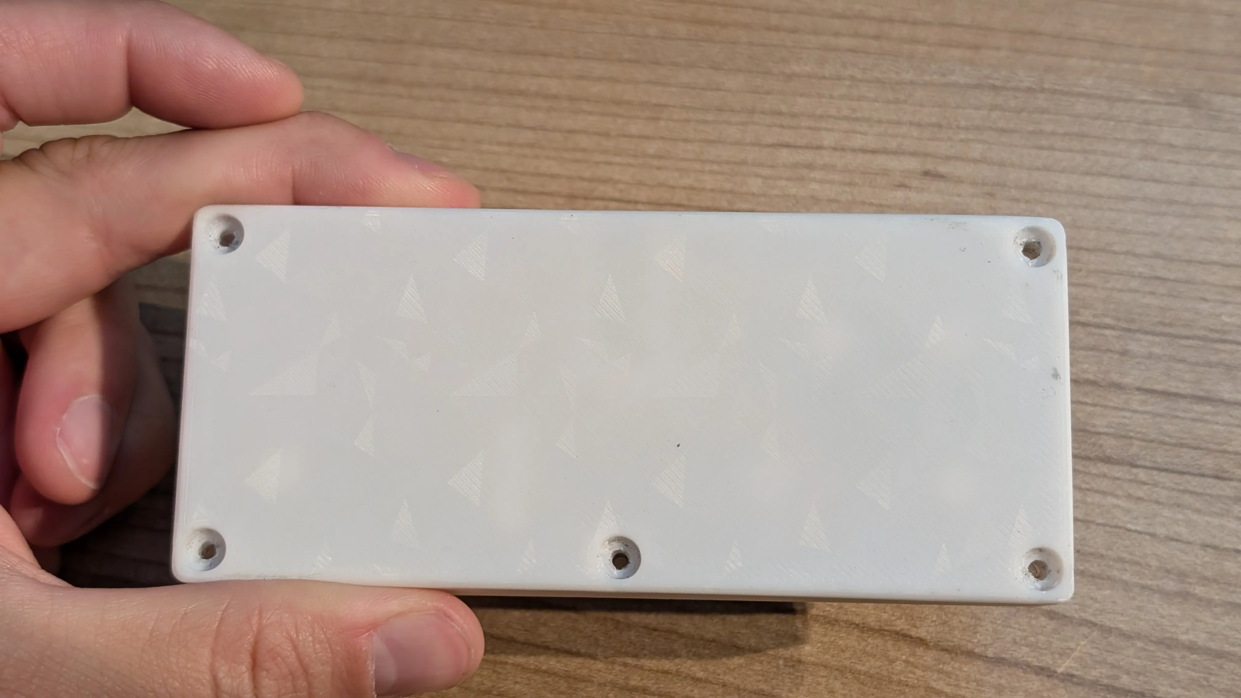 |
| 3. If the buttons wobble a little due to printing tolerances, you can place a thick sheet of plastic between them. | 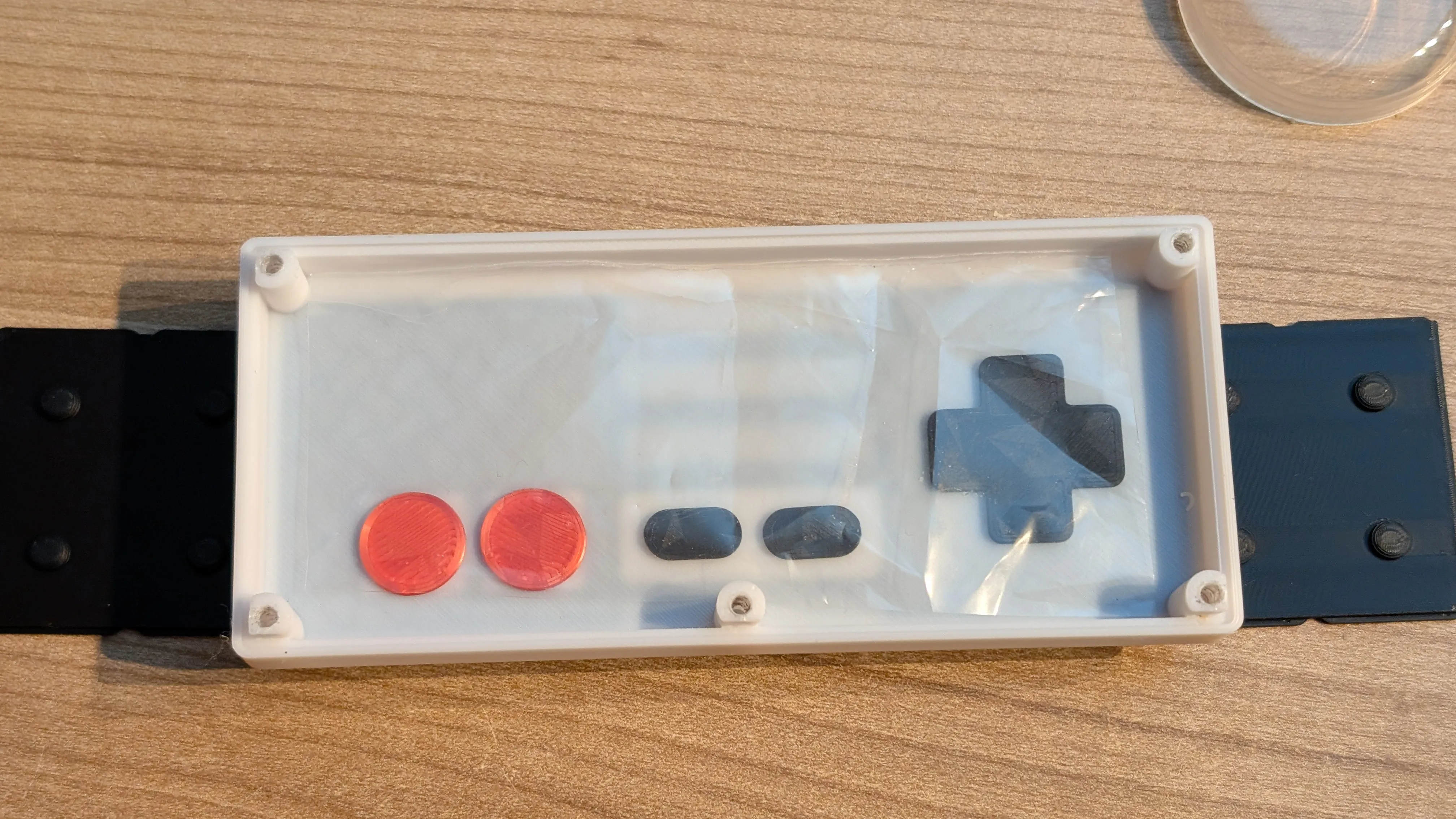 |
Done! Your NES controller is now ready. Have fun playing!
Code:
import time
import board
import digitalio
import usb_hid
from adafruit_hid.keyboard import Keyboard
from adafruit_hid.keycode import Keycode# === CONFIGURATION: Wiring ==============================================
# WIRING defines how the buttons are connected to the pins:
# "PULLUP_GND" → The pin reads HIGH when the button is open, and LOW when the button is pressed.
# "PULLDOWN_VCC" → The pin reads LOW when the button is open, and HIGH when the button is pressed.
WIRING = "PULLUP_GND" # or "PULLDOWN_VCC"
# =======================================================================# Initialization of the keyboard object, which can send keystrokes to the PC
kbd = Keyboard(usb_hid.devices)# Helper function to get the correct pin for different boards
# name_d: Pin name on a "classic" Arduino-like board (D5, D6, …)
# name_gp: Pin name on a Raspberry Pi Pico/board with GP pins (GP5, GP6, …)
def pin(name_d, name_gp):
if hasattr(board, name_d):
return getattr(board, name_d)
return getattr(board, name_gp)
# =======================================================================# === PIN MAPPING: Which button is connected to which pin ================
# PINMAP defines the physical connection of the buttons to the pins.
PINMAP = {
"UP": pin("D5","GP5"), # Arrow key up
"DOWN": pin("D4","GP4"), # Arrow key down
"LEFT": pin("D6","GP6"), # Arrow key left
"RIGHT": pin("D3","GP3"), # Arrow key right
"A": pin("D7","GP7"), # Action button A
"B": pin("D8","GP8"), # Action button B
"START": pin("D9","GP9"), # Start button
"SELECT": pin("D10","GP10"), # Select button
}# =======================================================================
# === KEYMAP: Which keystrokes should be sent to the PC ================
# KEYMAP defines which keycode is sent when a certain
# button is pressed. This can be customized individually for each game.
KEYMAP = {
"UP": Keycode.UP_ARROW, # Arrow key up
"DOWN": Keycode.DOWN_ARROW, # Arrow key down
"LEFT": Keycode.LEFT_ARROW, # Arrow key left
"RIGHT": Keycode.RIGHT_ARROW, # Arrow key right
"A": Keycode.SPACE, # Example: Jump
"B": Keycode.LEFT_CONTROL, # Example: Sprint / Shoot
"START": Keycode.ENTER, # Start/Confirm
"SELECT": Keycode.TAB, # Select/Switch
}
# =======================================================================# === Initialization of pins and states =================================
io, pressed = {}, {}
for name, p in PINMAP.items():
di = digitalio.DigitalInOut(p) # Initialize pin as DigitalInOut
di.direction = digitalio.Direction.INPUT # Define pin as input
di.pull = digitalio.Pull.UP if WIRING=="PULLUP_GND" else digitalio.Pull.DOWN
# Enable pull-up or pull-down resistor
io[name] = di # Store pin object
pressed[name] = False # Initial state: Not pressed# Function that checks if a button is currently pressed
def is_pressed(btn):
return (btn.value == False) if WIRING=="PULLUP_GND" else (btn.value == True)# =======================================================================
print("Keyboard emulation started. Focus the browser window and test.")# === Main loop: Poll buttons and send keystrokes =======================
while True:
for name, di in io.items():
now = is_pressed(di) # check current state
if now and not pressed[name]: # button has just been pressed
kbd.press(KEYMAP[name]) # send keystroke to PC
pressed[name] = True # set status to pressed
elif not now and pressed[name]: # button has just been released
kbd.release(KEYMAP[name]) # release keystroke
pressed[name] = False # set status to not pressed
time.sleep(0.01) # short pause to reduce CPU load
License

You shall not share, sub-license, sell, rent, host, transfer, or distribute in any way the digital or 3D printed versions of this object, nor any other derivative work of this object in its digital or physical format (including - but not limited to - remixes of this object, and hosting on other digital platforms). The objects may not be used without permission in any way whatsoever in which you charge money, or collect fees.


Comment & Rating (4)