
AeroFold V2: Folding VTOL 1.6m Plane


Print Profile(1)

Description
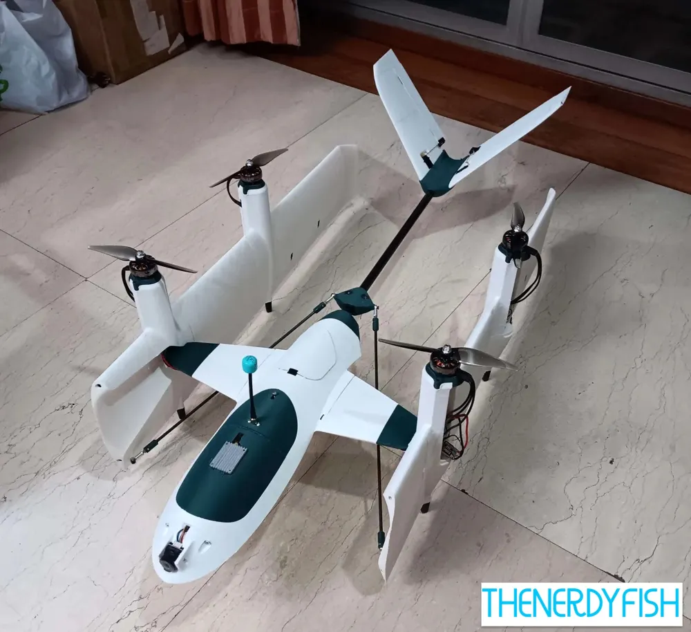
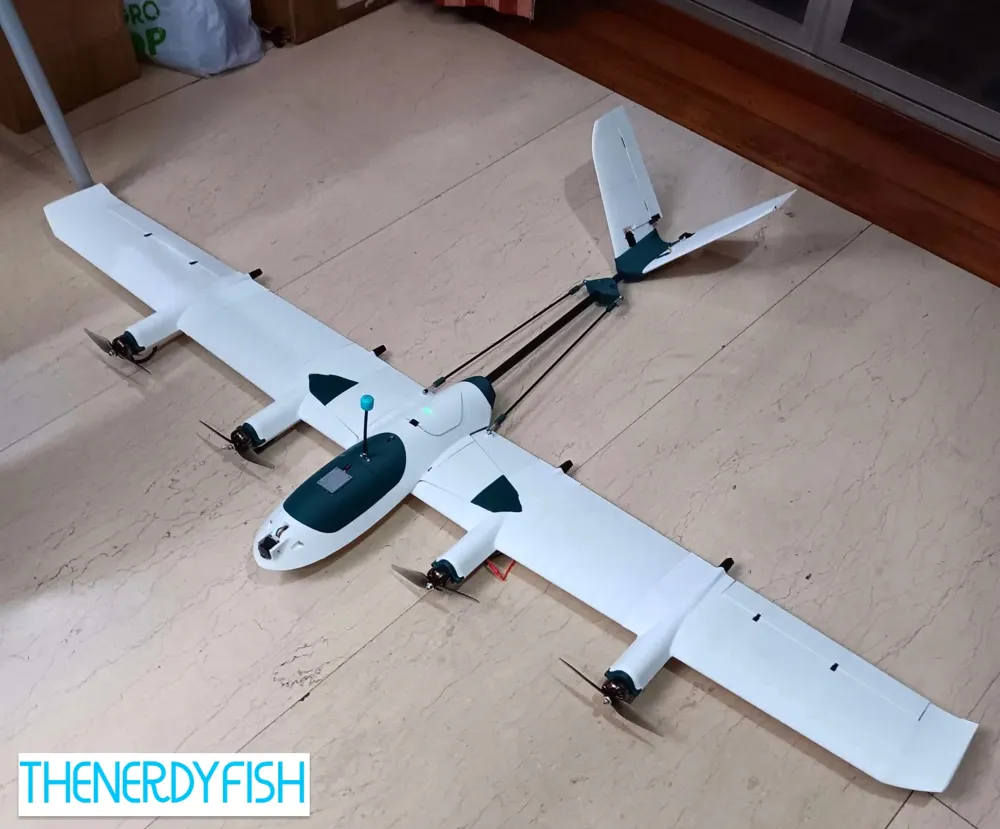
My finished design, complete archive, fully flying, DIY, 3D printed, folding VTOL airplane!
V2 is finally ready, tested, documented, and meticulously set up in the slicer– ready for printing. See V1 here!
Building one? Curious? Want to follow along with 100's of other builders making this? Join my highly-organized Discord! [discord invite]
Follow the design here with a ❤ / Collection / Boost, follow my Instagram, and visit the thingiverse page for V1!
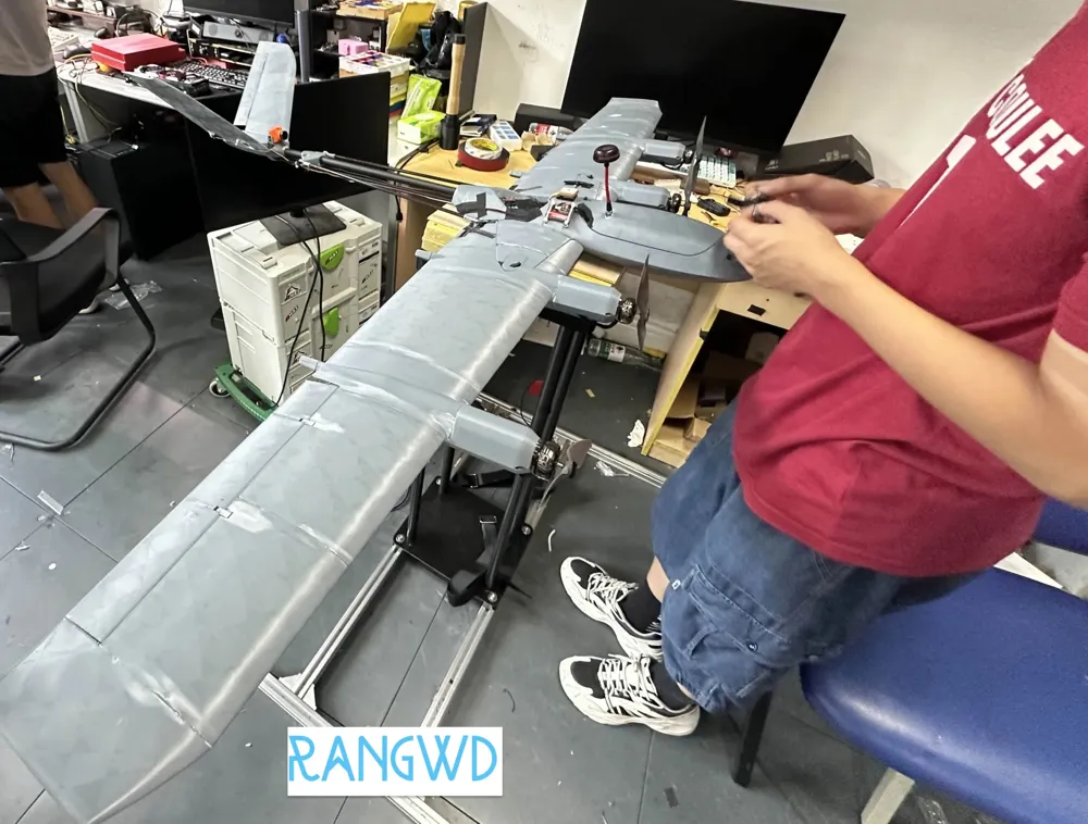
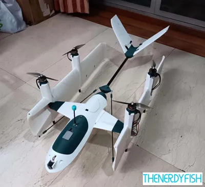
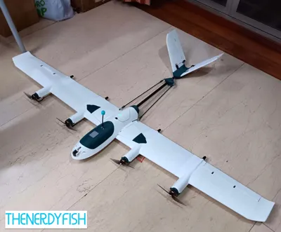
Cover photos are from 5prop's successful maiden flight. See my edited reel on instagram and youtube as well!
Specs:
- Wingspan 1.6m
- Minimum battery weight (to fit CG): 50Wh. Maximum ~240Wh with 2170 cells
- Aerofoil Profile: NACA-4414 at root tapered to NACA-4412. High aspect ratio, ultra efficient.
- Wing Incidence Angle: 2deg
- Dry weight (as configured below): ~800g (still to be finalized)
- Stall speed ~20mph (depending on battery load)
- Features
- 4-motor, works with standard 5" FPV quad motors (I used 7" Eco2 motors)
- Four servos for control surfaces (V-Tail + ailerons)
- Novel wing folding mechanism with only 1 additional servo
- Print-in-place tube clamping system for rigid carbon spar utilization
- Socketed printed wing segment fit inside each-other for perfectly flush & strong results
- Modular nose allows for easy vtx/camera system swaps or choices.
- Ailerons use fully printed axle pivoting system
- V-Tail control surfaces attached with TPU inserts
- All printable on an A1 Mini
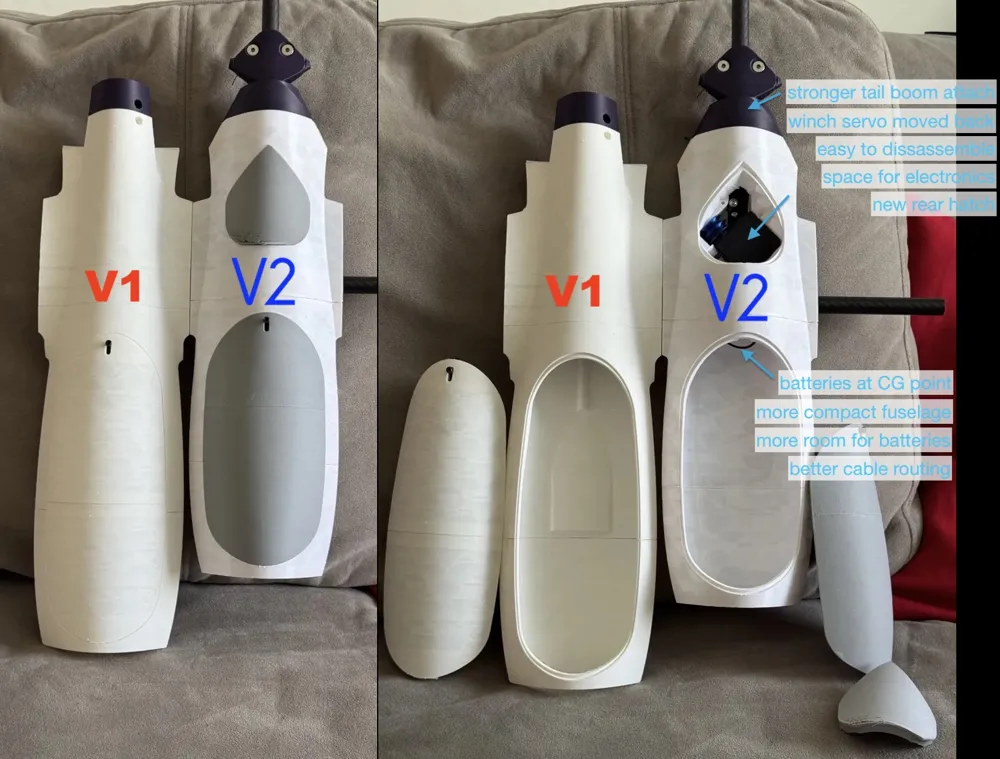
What's new in V2
- Fuselage
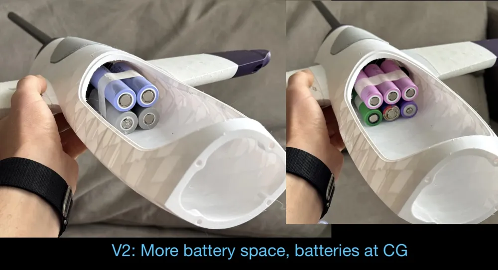
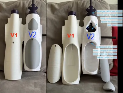
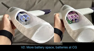
- Massive internal area increase. More batteries, electronics, etc
- And the fuselage length actually decreases! Better for CG
- So more compact fuselage yet has more space
- New blended design: fuselage blends into wings
- Tilt-mechanism winch servo now moved into new rear compartment
- Leaves room for batteries *at* the CG point
- Means: much more battery carrying capacity/flexibility
- Easy winch servicing, more modular removal / disassembly
- New dedicated servo hatch
- Room for electronics in the rear hatch area!
- Stronger tail boom attachment with far more extensive "rigid insert" part and now 6mm spar reinforcement
- Main hatch now has compliant printed latching mechanism
- Much easier cable routing: into wings, into tail, etc.
- Vastly improved tail boom clamping.
- Massive internal area increase. More batteries, electronics, etc
- Wings
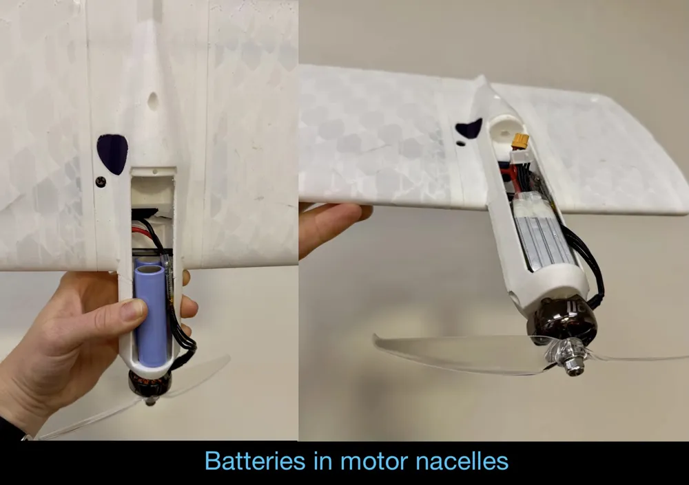
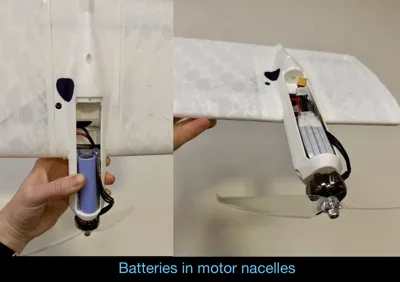
- Redesigned motor nacelles, larger, fits batteries
- Each can now fit 2x 2170 lithium ion cells or 1x 750mah 4s pack
- Nacelles are longer, put motor wight more forward, fixes airplane-mode CG
- Nacelles are now HALF THE WEIGHT
- Now carbon-spar-reinforced LWPLA instead of heavy CFPLA
- Down to ~30g from 60g, including the insert
- Much easier to work on, route wires, and fit electronics
- Redesigned motor nacelles, larger, fits batteries
- Tail
- Redesigned main tail part
- Bearing carrier part snaps/bolt-in for super easy servicing
- Easily removed, easy access to the V-Tail servo connector path through the main tail boom exit
- Now uses one bearing part everywhere (5mmID x 10mmOD) – same as the shuttle part
- Shuttle part (moves along tail boom) now stays more centered with redesigned cable path
- Redesigned main tail part
- Test fit part
- New test-fit part, please print, measure, test-fit, and dial-in!
- See the documentation below
Boost Me (for free)
Pretty fancy, eh? It's been lots of time and effort! Worthy of a boost?
Folding mechanism
Novel approach for folding mechanism is to use a dual-side pulley system using kevlar line– driven by a sail-winch servo situated forward of the CG. Very strong, perfect transition speed, nearly no play, light weight, and has closed loop control (can be commanded to any mid-transition position).
Flight Characteristics Simulation
Simulated flight dynamics using ecalc, results screenshots:
- Airplane mode (uses two motors only)
- Quad mode.
Parts List
Aliexpress pages randomly disappear– so I try and link to generic searches, screenshots, and amazon too.
Parts list, for now, is the same as V1. (the V1 page was updated for many of the v2 parts)
- Slicer:
- Orca Slicer is very highly recommended! It's a fork of Bambu Studio that adds tons of features and adds support for most other 3D printers!
- Bambu Studio slicer can work, it's just missing several helpful settings are only available in Orca.
- Highly recommend NOT using Cura/etc. It doesn't support multiple plate organization, modifier objects, etc.
- Filament
LW Filament
Highly recommended! Without standard filament it will be 2x the weight for no appreciable benefit.
- CF-PLA for strong structural parts. I used this from Creality [amazon]
- CF filaments are much more rigid, many big parts are designed with small rigid inserts. PLA+ or PLA Pro may work.
- PETG for the hinge bolt sleeve for low-drag against CF-PLA.
- TPU for V-Tail hinges, bearing rollers, and landing gear.
- Carbon Tubes
- 4x 500mm 14mm diameter long carbon tubes, [amazon, ali, ali-search, screenshot]
- 4x 6mmX4.1mmx500mm [ali, screenshot]
- 4x 4mmX2mmx500mm (same as above)
- Electronics
- Winch Servo. Needs to be 6-turn servo (for transition actuation) Look for W5513-6T [amazon, ali, ali-search, screenshot]
- 4x Motors. Compatible with a large range of motors. I used Emax Eco2 2807-1300kv [amazon, emax]
- Props: on 4S with 1300kv motors– use 7 or 8" props like the Gemfan Flash 7042 2-blade.
- Flight controller:
- Recommended: An H7 model like the Kakute H743-Wing (what I have), Matek H743, etc
- May work, but unclear: SpeedyBee F405 Wing Mini. If Lua-scripting is necessary this will not work. TBD.
- Aileron servos: standard MG90S or similar micro servos are fine [ali-search]
- V-Tail servos: 4g mini servos, [amazon, aliexpress item S002M, screenshot]
- ESCs ~45A blheli. What I'm using. [amazon, ali-search]
- Hardware
- Imperial bolts:
(sorry! imperial bolts have very coarse threads which don't strip out into parts)- 10x #6-32 by ½" countersunk machine screws for tube clamps [amazon | ali example (choose 6-32, ½")]
- 2x 1/4-20 x 1-Inch bolts for main wing hinge. Countersink is also probably best: [amazon | aliexpress]
- Metric hardware:
- M3 Ball Joints (for transition push-rods) [amazon | ali search, screenshot]
- M3x20mm threaded rods (for transition push-rods) [amazon | ali-search, screenshot]
- Several M3 sizes used for transition push-rods, I recommend you get a M3 countersunk kit [aliexpress, alt, screenshot]
- Getting just 8mm and x 16mm should be enough.
- Optional: M3 heat-set inserts for modular Nose. Can also be glued. [ali search]
- Bearings / Pulley:
- 2x 5mmID 10mmOD 4mmW (MR105) [amazon | ali-search, screenshot]
- Kevlar chord, 50lb strength / 0.4mm diameter [amazon | aliexpress, search, screenshot].
- Used for the transition actuation winch system.
- Steel z-pushrods (for control surfaces– can use piano wire) [ali-search]
- Imperial bolts:
- Wiring
FEP Wire for power & servo lines
FEP Wire is stiffer, low friction, and smaller diameter. REQUIRED for routing through the hinge area.
Silicone barely works, only when wrapped in kapton tape (see below)- Power wire: FEP 18awg. [amazon | ali-search, screenshot]
- Servo wire: FEP 26awg. [amazon | same ali listing as above]
- Servo extensions
- Recommend custom crimping your own to be perfect length! Requires:
- servo-wire
- a servo crimp kit [aliexpress, ali-search, screenshot]
- and a crimp tool. [ali-search]
- Alternatively (but also helpfully) Pre-made servo extensions [aliexpress, ali-search, screenshot]
- Recommend custom crimping your own to be perfect length! Requires:
- 3.5mm Banana Connectors [aliexpress, ali-search, screenshot] to make the wiring harness un-plugable and modular.
- Kapton Tape: you should have some handy. Useful for wrapping around wire bundles for low-friction through the hinge as well as building batteries, thickening carbon spars, etc. AKA High Temp Polyimide Tape. [ali-search]
- More documentation coming soon.
Batteries
This is designed to be very flexible with batteries! Many options work great.
For the motors I've specified it's intended for 4S packs. Other motors/props can handle different voltages.
- Minimum-sized: ~1200mAh 4S lipo pack, mounted in the center fuselage. Flies efficiently for 10 to 15 minutes.
- Min-size means minimum weight. Minimum weight means minimum stall speed. Always fly your first test flights with a lightweight option.
Motor Nacelle Pod Mounted battery options:
Under development! Currently designed to fit either:
- Maximum capacity: 8x 21700 cells, 2 in each motor nacelle for a 4s2p setup. Recommended cell: Molicel P45B [imr]
- Maximum power: 4x Tattu 4S 750mAh lipo packs, one in each nacelle. Will be testing these as well.
This is till under testing for CG, wiring, etc.
- Minimum-sized: ~1200mAh 4S lipo pack, mounted in the center fuselage. Flies efficiently for 10 to 15 minutes.
Slicing & Printing:

The 3MF is set up with extensive use of modifiers to make perfect ultra lightweight and ultra strong parts, important for aircraft printing.
Happy to export STL and/or STEP files for everything as-is right now, just per person on my discord so I can get feedback, tips, problem reports, and improve the project while it's under development.
→ Join my discord ←
General Print Settings
- Filament: Lightweight filament for most parts. See the exploded diagrams below and the parts list.
- Infill: Cubic, 6% (not adaptive cubic!)
- Walls: 1 perimeter in most places for most parts.
- Seam positioning: Nearest. Helps lots for LW filament
- Wall generator: Arachne. Enables thin walls that actually print well.
- Support: None for most parts. See exceptions.
- Exceptions:
- The bottom and top ~8mm have modifiers to double the infill (to 12%) and use 2 walls.
- All layers where bolts thread into also use 2-walls & 2x infill.
- All nacelle parts (w1 & w3) require support and I prefer them with 2 walls. For now. Working on some changes.
- Please use Orca Slicer and refer to my 3MFs for all settings and ask me any questions/clarifications!
- When you switch printers to non-bambu options it may reset settings! Use a second window as reference.
Build Video
V1 build video, for now. Will re-make with V2 soon.
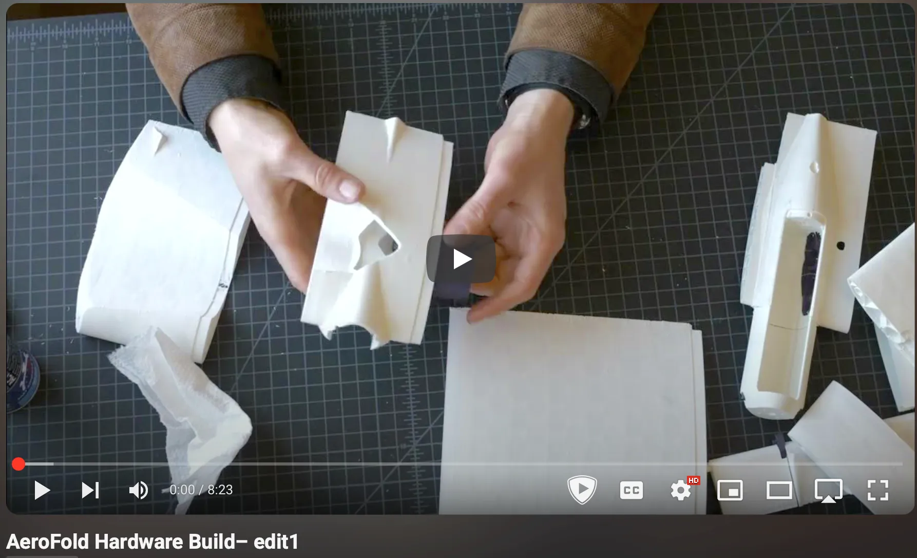
Made a video walking through the build process. Happy to make future videos on things like tail assembly, wiring, winch setup .. let me know!
Organization & Assembly

All parts are named for alphabetical sorting:
- fuselage * have all fuselage parts
- w* are all the wing parts. Must be mirrored and printed again for the right wing.
- tail * Are all the fin parts that also are mirrored and printed for the right side.
- vtail * Is the joiner base that the fin parts slot into.
- shuttle * Moves along the main boom to drive the actuation.
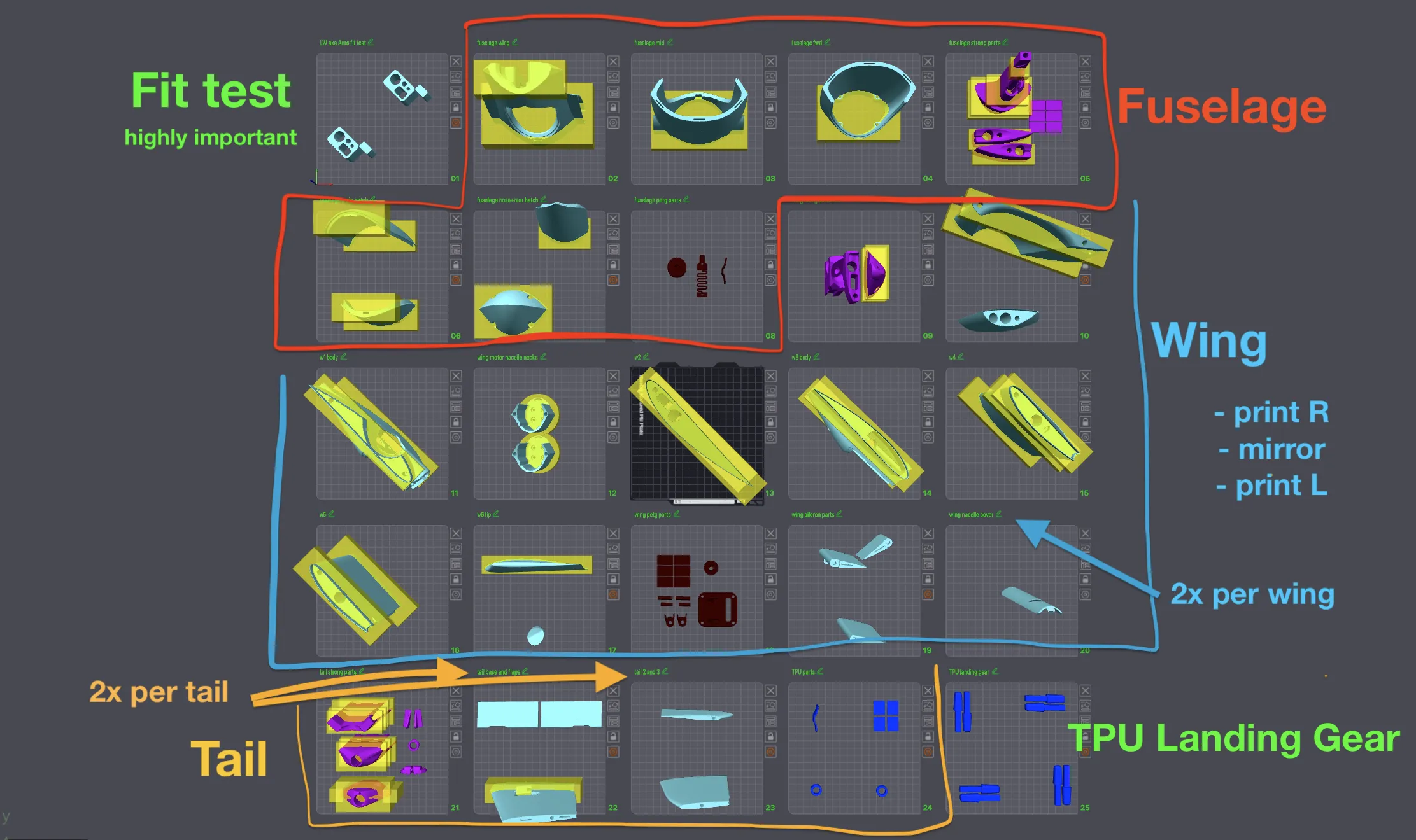
The 3MF file should contain all parts with all my recommended overrides and organized into sections:
Colors as seen in the screenshot below: Light blue: LW-PLA, Purple: CF-PLA, Dark Red: PETG, Royal Blue: TPU.
- Fit Test
- Print to test that your carbon spars fit.
- Cut off the external cube and make sure it fits inside the slot
- Use calipers to verify the wall thickness matches your slicer wall thickness
- Especially important for foaming LW/Aero filaments
- Fuselage
- Pretty straightforward. Print each plate once.
- Wing
- Print each plate once (hatch plate twice) and dial in your settings.
- Then mirror each part and print again for the left wing
- Tail
- First bed is printed once. Second two beds (the LW parts) are printed twice, only mirror the “tail 1 base.stl” file
- TPU Landing Gear
Fuselage Parts

- Green is glued with CA glue.
- Fuselage nose is configurable with several different camera setup designs. O3, O4 Pro, Pan mount servo, and gimbal mount is WIP.
Wing Parts
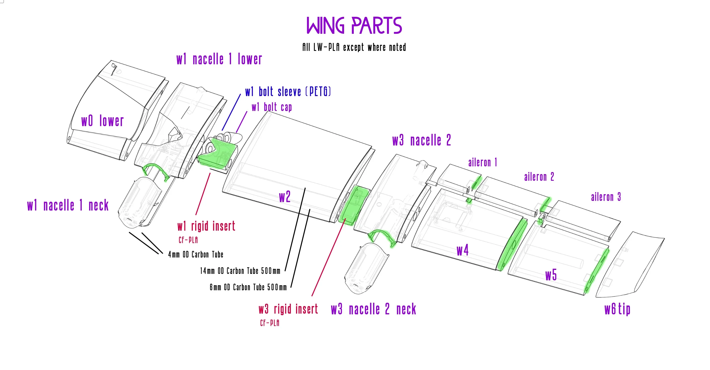
- Green is glued with CA glue.
- If non-glued parts are too loose add a loop of kapton tape around the ends of the spar that goes through that part to add thickness.
- Not labeled:
- Aileron hinge parts
- Aileron servo cover/holder
- Join tabs
Tail
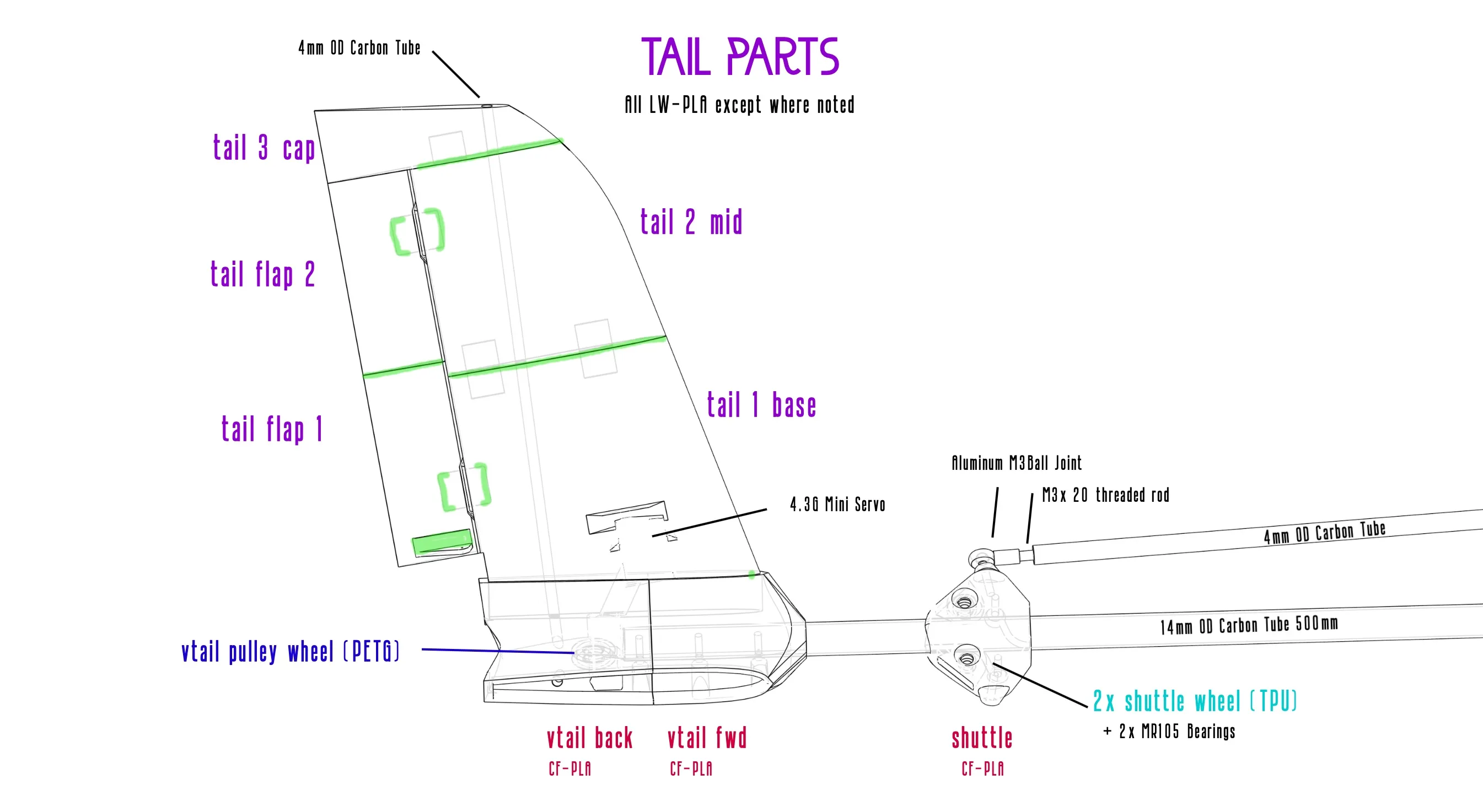
- Green is glued with CA glue.
- Not labeled:
- Join tabs
- Servo linkage
Fixes, feedback? Something could be clearer? Please say so in my discord!
Carbon Spar Sizing
Using a simple hacksaw cut your carbon spars to size.
It's recommended to wrap tape around the cut area to stabilize the outer fibers and mark the cut position.
Double check the length of each in the airframe before cutting.
- Each Wing
- 1x 14mm x 500mm main wing spar
- 1x 6mm leading edge wing carbon spar can be a maximum of 687mm long. 500mm is plenty though, that's what I used.
- 1x 6mm trailing edge wing carbon spar needs to be 180mm long
- 4x 4mm nacelle support spars are 98mm long, 2x per motor.
- Fuselage
- 1x 14mm x 330mm main fuselage-to-hinge spar
- 1x 6mm x 274mm secondary fuselage-to-hinge spar
- 1x 6mm 298mm (maximum) spar to support the bottom of the fuselage. I recommend cutting it at 274mm to match above.
- Tail
- 1x 14mm x 500mm main tail boom
- 2x 4mm carbon spar 230mm each (one left, one right side)
- Shuttle system
- 2x 4mm carbon spar pushrods are 317mm each
Winch servo / kevlar rope installation process
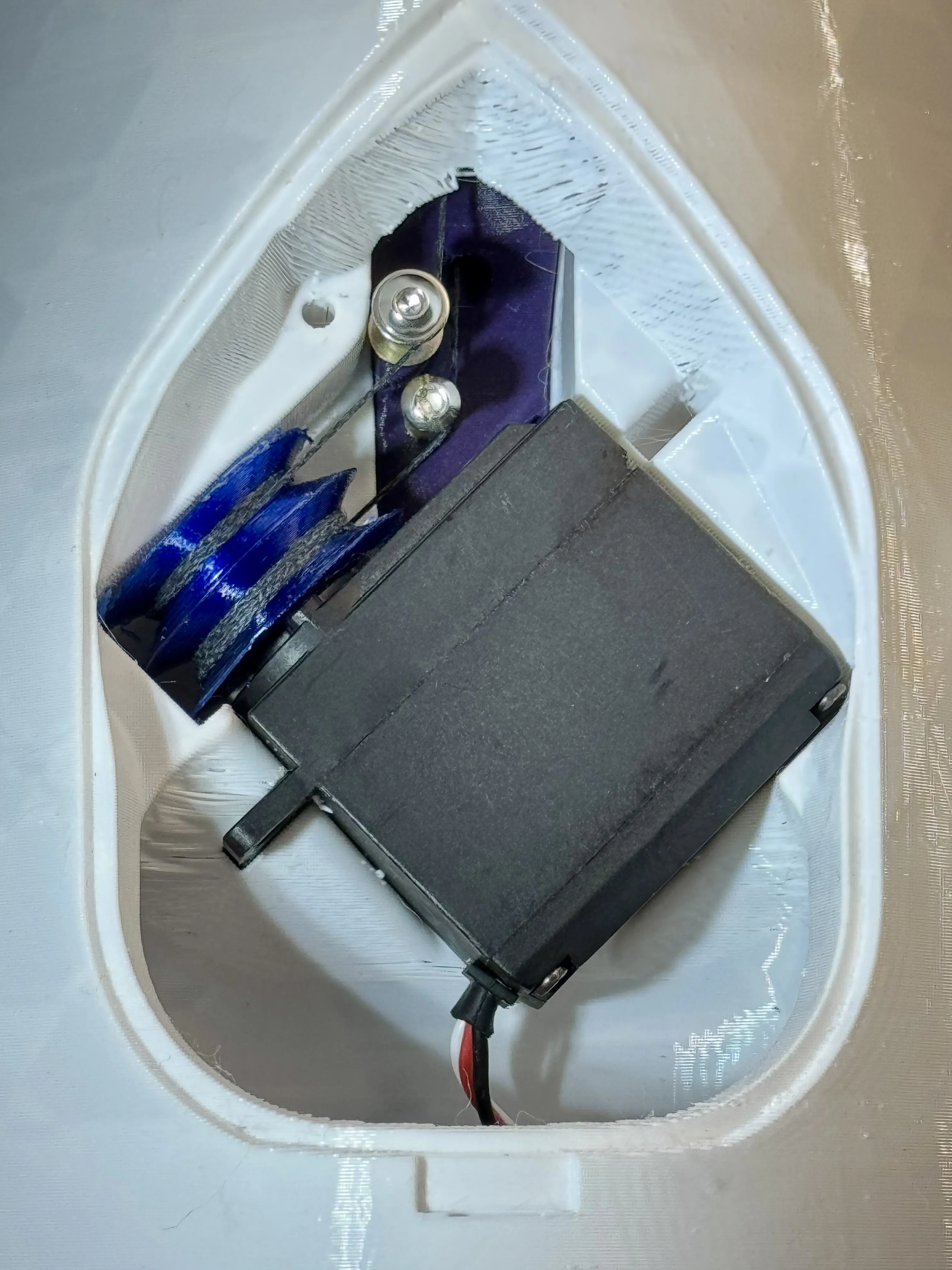
Center the winch servo at 1500ms
- Cut the rope to-length. Safe over-estimates are 0.6m and 1.2m (get TODO accurate lengths)
- anti-fray: it's impossible to melt the ends of kevlar rope! use a drop of CA glue instead, using a paper towel to pull flat.
- tie one end of each rope to an M3 nut. This terminates the rope so they stay captive on the pulley.
- Install the ropes into the pulley. Shorter rope on the inside slot, closer to the servo. Longer on the outside.
- Wind 4 turns of rope on both sides of the pulley.
- clockwise on the inside, closest to the servo
- counterclockwise on the outside
- use a piece of tape or a small clamp to temporarily hold the wraps in place
- Feed the rope out
- inside|shorter|clockwise rope feeds through the small exit hole in the fuselage back part
- outside|longer|CCW rope feeds through the tail boom exit (later goes through the whole boom)
- press fit the servo into position in the fuselage wing part
- install the rope-redirection standoffs
- Install the boom, shuttle, and vtail part at the end.
- install the vtail insert, feeding the rope through the gap between the part and the bearing&wheel
- Shuttle setup
- center the shuttle
- Feed the rope though the pathways for each rope
- Pull the rope tight, wrap the rope around your M3 bolt, tighten bolt to hold in-place
- Carefully run the servo back and forth. The rope will loosen– so re-tighten by re-bolt tightening one end once or twice to get the system tight.
- Carefully set your autopilot endpoints to values that don't over-actuate in either direction
Autopilot Setup
Documentation is a TODO. Right now it's successfully flown with full transitions with iNav.
Center of Gravity, CG/CoG
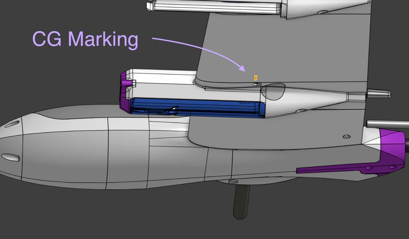
The CG is marked on each wing with a balance point bump. This is the standard way to mark and test CG on models.
Sharing & License & Such
The LAST thing I want to do is restrict anyone from sharing. But. PLEASE share links to this makerworld page, not any 3MFs or STLs. Here's why:
- This is under active development. The design WILL CHANGE and get better.
- The documentation is really important here, and I'm sure there's stuff I'll be adding as feedback comes in.
- The community is important, I want people to reach out and join the discord not download some STLs and go it alone.
- It's just a super dick move to repost designer's stuff. I've spent a long time making, testing, and documenting this and my only reward is that little stupid ‘like’ counter, download counter, and photos/stories from users. DON'T DEPRIVE ME OF MY ONE SENSE OF SELF WORTH
The specific license is “Standard Digital File License,” Noncommercial. Spam “remixes” have been a problem, please reach out if you have some remix part ideas. If you'd like to print this commercially then reach out by opening a new thread on discord and we can talk. Flying professionally using my designs is fine– though please do consider donating some proportionate amount to support my work!
License

You shall not share, sub-license, sell, rent, host, transfer, or distribute in any way the digital or 3D printed versions of this object, nor any other derivative work of this object in its digital or physical format (including - but not limited to - remixes of this object, and hosting on other digital platforms). The objects may not be used without permission in any way whatsoever in which you charge money, or collect fees.


Comment & Rating (103)