
Print Profile(0)
Description
Key Features:
- No need to adjust the position for limit switches!
- Automatic scheduling based on geo-location and sunrise/sunset times.
- Durable and reliable due to stall sensing, high torque motor, and lubricated gears.
- Low cost.
Introduction:
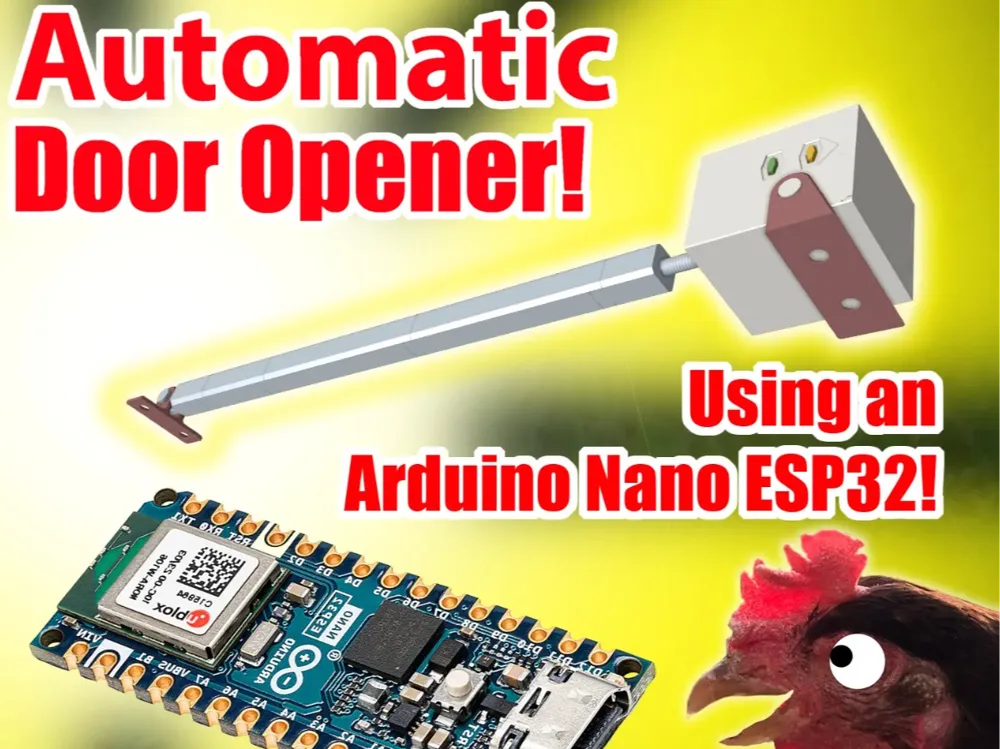
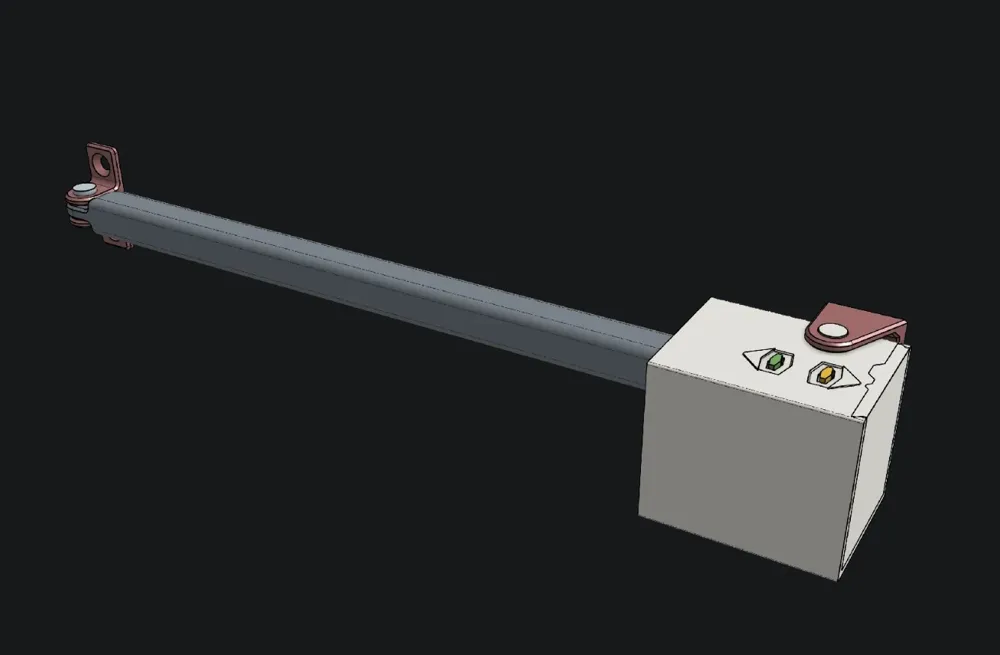
Over the past few years, I've been a little obsessed with linear actuators. Primarily for building an automatic door opener for my 3 chickens in their little coop. This is the latest version in which I set a few design challenges for myself:
- As little purchased hardware as possible.
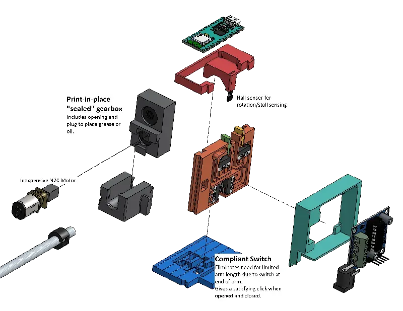
- Integrate some cool design features: (print-in-place gears, compliant mechanism)
- No dependency on cloud services.
I've learned a lot from this project, and I'm going to integrate it with the other things I've learned to provide a versatile and configurable linear actuator to the community in the future. I'll soon be releasing an earlier model that uses HomeKit integration and a more powerful motor. I hope this version is helpful, if not in practical use, then in inspiration to keep creating and sharing!
Features:
- Automatic scheduling based on sunrise/sunset times.
- Sealed print in place gearbox.
- A compliant mechanism for pressure sensing when the door is opened or closed
- Works on sliding or hinged doors.
- Works at any length.
- Minimal hardware.
- Cheap/inexpensive to build.
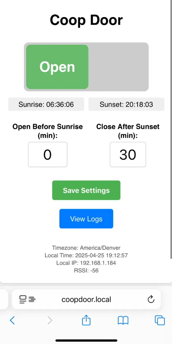
- Local web interface and easy to connect to WiFi.
- OTA firmware updates using ESPOTA.
- Stall sensing prevents the motor from burning up.
Video:
I know this looks incredibly slow, but it is extremely versatile while using an inexpensive N20 motor that does 150 RPMs which it uses to exert about 5 lbs of resistance to know when it's fully closed or open.
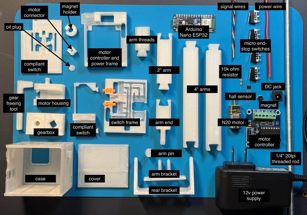
Purchase Parts List:
https://a.co/d/5Lyl0oL - Arduino Nano ESP32
https://a.co/d/aMI8NGh - N20 Motor
https://a.co/d/0rxfvJf - Assorted (6x2mm) Magnets
https://a.co/d/91HWrko - L293D Motor Controller
https://a.co/d/1Y54UDb - Micro limit switches
https://a.co/d/i87Jdo0 - A3144 Hall sensor
https://a.co/d/aAhLmfs - DC 005 jack
https://a.co/d/2s0st0w - 12V 1A DC power supply
https://a.co/d/4cqYGoR - 10K Ohm resistor
https://a.co/d/1R1U2zu - ¼" 20tpi Threaded rod
https://a.co/d/61qFu9V - 24ga stranded wire
Instructions:
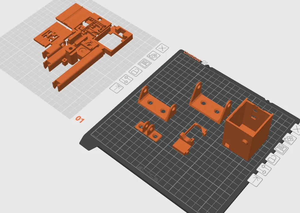
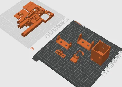
Notes: The 3MF file is for print layout suggestions. The full step file can aid in assembly and modification if needed. Thanks!
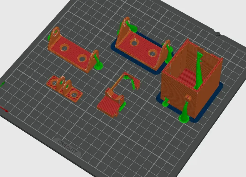
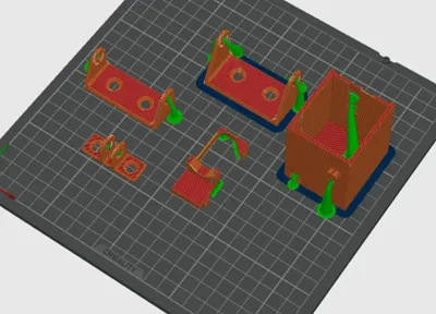
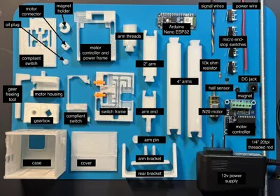
Print all parts. Supported items and the gearbox should be on separate plates. Printing the gearbox at a 0.15mm or 0.16mm layer height will ensure smooth operation. Lower extrusion or flow rates on the gearbox until you can print it out and break the gears free. Use the square key tool (L-shaped) and a ¼" 20TPI bolt to leverage the gears until they wiggle. Add oil or grease through the oil hole and seal with the screw-in plug.
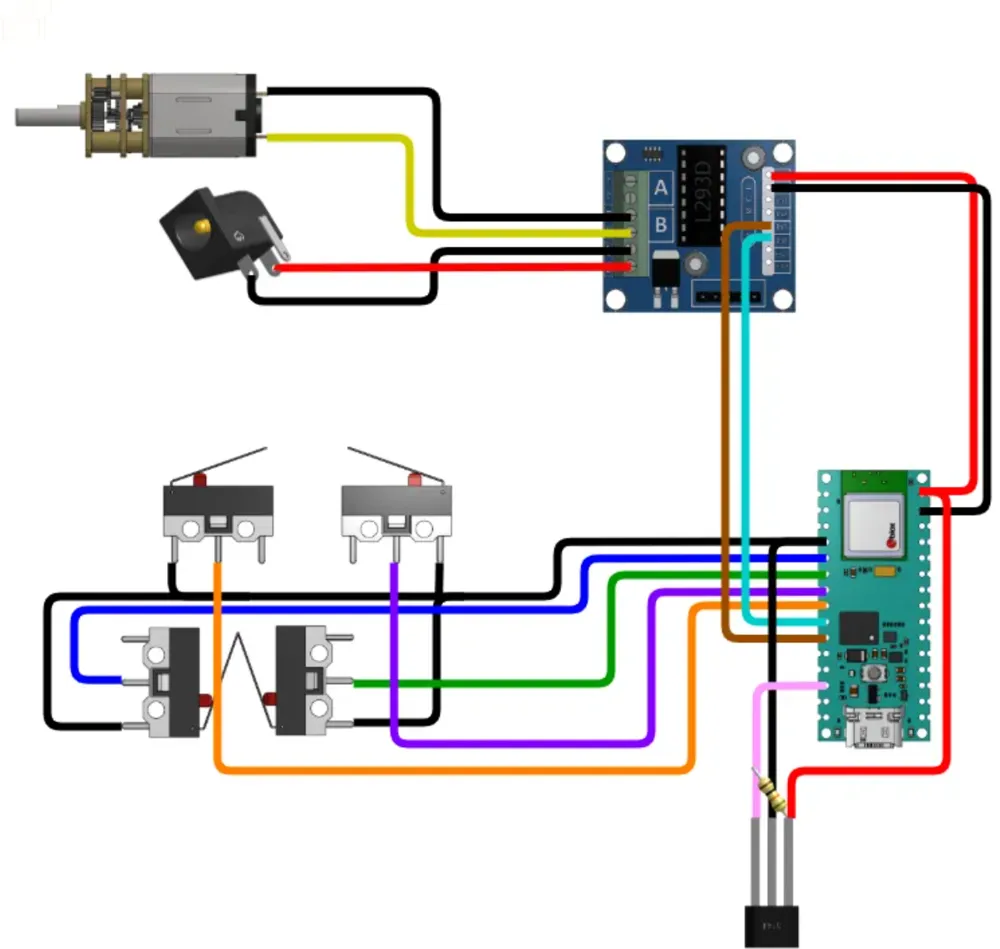
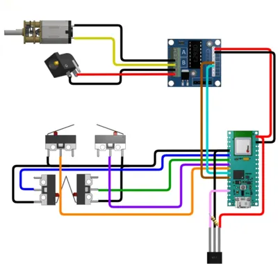
According to the diagram, place the limit switches in the switch frame and solder wires. Route the wires wherever feels easiest. These should all go through the opening at the top of the switch frame.
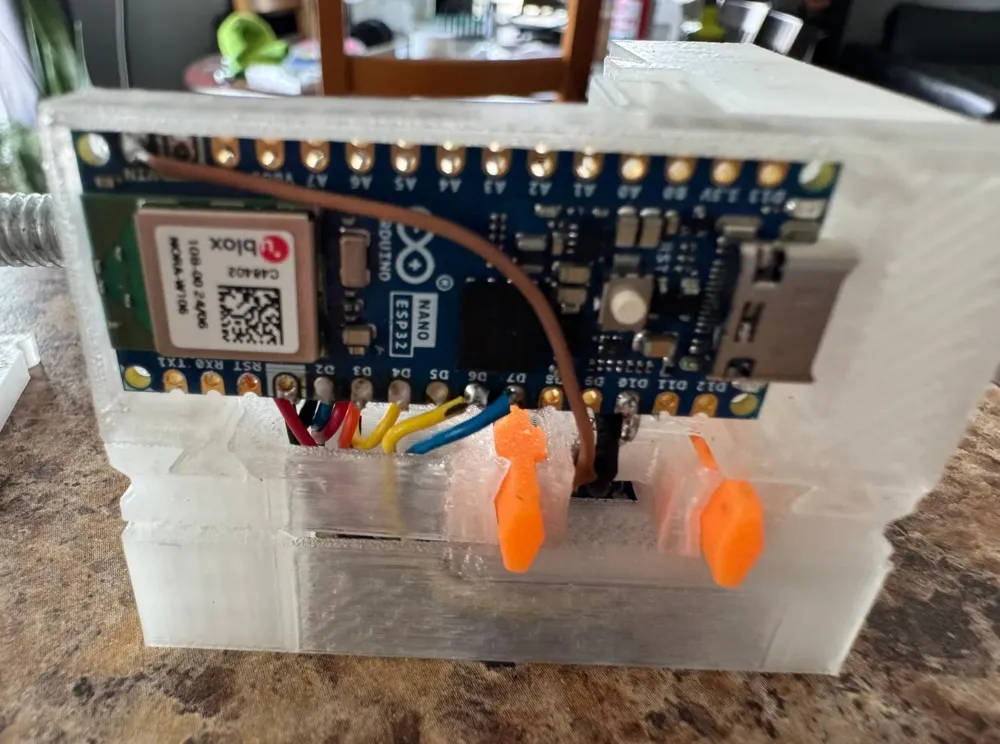
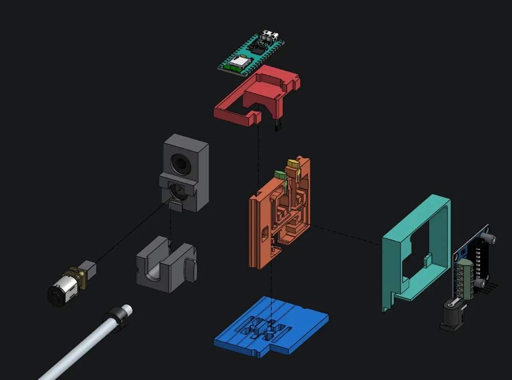
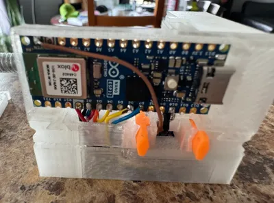
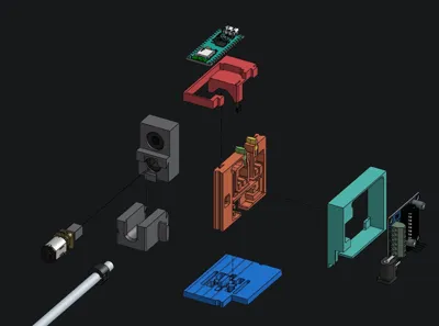
Insert the hall sensor into the Arduino frame (this should go in from the opening at the end of the protrusion, with the text facing out. Connect the Arduino frame to the switch frame. Load the code onto the Arduino board using a USB cable. Any changes or updates can be done OTA after the initial loading. Insert the Arduino board into the Arduino frame and connect the wires according to the wiring diagram.
Insert the motor controller into the motor and power frame. Removing the header from the controller might make soldering wires directly to the board easier and more secure. Attach the wires to the motor controller frame and then to the Arduino board.
Solder the power wire to the DC jack and the motor. Place the DC jack in the power frame, estimate the length needed to connect to the header, and then clip and tin the tips of the wire before connecting. Do the same for the motor wires.
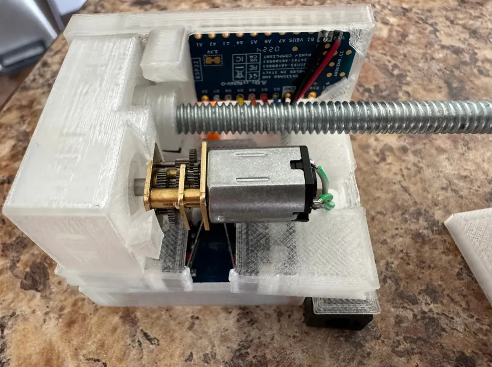
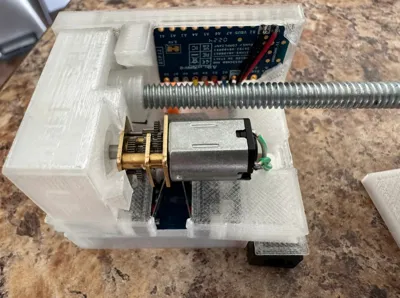
Press the motor connector onto the motor. Slide it into the gearbox and connect the motor housing to the gearbox, securing the motor in place.
Screw the magnet holder about 1" up the threaded rod. Place some super glue on the end of the threaded rod and screw it into the gearbox. Screw the magnet holder up to the gearbox and place the magnet in. The A3144 hall sensor is unipolar, so polarity matters. The south pole of the magnet is detected when facing the sensor. It might be easier to just assemble and then reverse the magnet later if it seems like the stall feature is being triggered.
Test all the connections using the continuity function on a meter to ensure they behave as expected.
Place the gearbox onto the compliant mechanism, and then the rest of the assembly on top of it. Connect the motor to the motor controller. Slide everything into the case and then slide in the cover.
Assemble the arm. Once powered on and started, use the in button to thread the arm down the threaded rod.
Finally, attach the brackets to the coop and door, install the opener, and test!
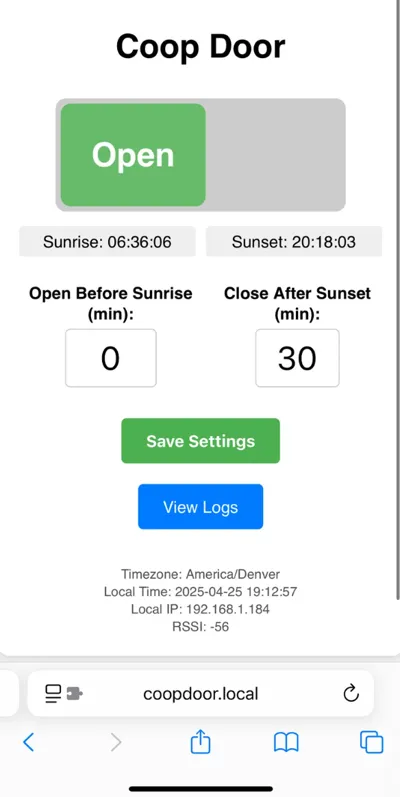
You should see a new WiFi hotspot “CoopDoor”, which you can connect to with your phone. The password is chickens! (with an exclamation mark at the end). Once connected, you will be walked through connecting the device to your WiFi network. Once the device connects, you should be able to access it by going to http://coopdoor.local . This will allow you to control and monitor the opener.
Code for Opener:
https://github.com/afterwords/printables_coopdoor
Mark Rober's Arduino crash course for beginners:
https://www.youtube.com/watch?v=yi29dbPnu28
Quick tutorial from makeuseof channel for using PlatformIO on an Arduino board:
https://www.youtube.com/watch?v=dany7ae_0ks
License



Comment & Rating (3)